
Ldmos 23cm Pa
This project was a pain. Several LDMOS was burnt. I do not blame the Chinese sellers on EBay that they know them selling fake LDMOS, however some of them are. 2 of the sellers gave me full refund. One gave me a compensation. I asked where they get their stock of components from, however no answer. I contacted NXP and send them pictures how the LDMOS looked inside, and one of them where clearly a fake. It is tempting to buy, since the price is low.
The board was purchased from Anders SM5DGX, a well-known radio amateur. He has built tremendous of high power PA’s. This board is his design, and he sells boards when available.
I have built some other LDMOS PA’s and I must confess that this one is not a walk in the park. The board needs to be soldered to the heat spreader. And the other components should be soldered with high temperature solder before that. The TC-350 is a delicate board, if using a traditional soldering iron you must be light at hand. If you press to hard you will see it on the earth side. And the used IC’s for the bias is small. W6PQL do not solder his boards, however he has a kit with thin discs and a solution with PTFE blocks which put press on the board to keep good contact with earth.
If it wasn’t for Anders I guess I never would win this match. He helped me a lot. I wanted to say this because if you know that above seems to difficult, buy a ready built board.
Now to more fun things...
Time to fix more power on 1296 MHz. There are quite a lot of options of LDMOS devices at different power levels. Surplus devices can be found if you know a ham working in that field. eBay is also flooded by different surplus, which sometimes are not cheap at all when ship cost is added.
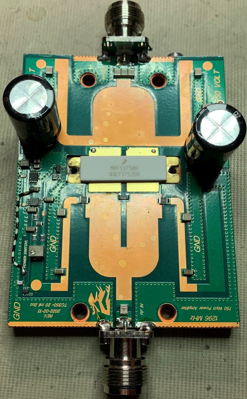
I have made some 23cm PA’s around 100W maximum output. It would be nice with 3-6db more. SM5DGX, Anders has made a nice pcb board with TC-350 laminate. This board uses the NXP MRF13750 LDMOS and can deliver 600W out. This is way more than what my antenna preamp (MVV 1296 VOX) can handle, which is about 200W SSB/CW and 100W digi. And the 44 element Yagi can handle 500W.
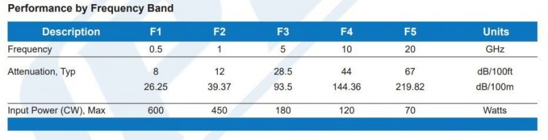
I have 14m of LMR-400 to the antenna, this means that I will lose about 2db. This means that 325W out from the PA will be 205W at the preamp.
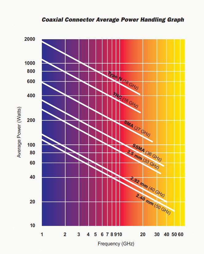
Since 350W will be the maximum output I can use (with this preamp) I could go for SMA connectors in the PA. They are rated 600W @ 1GHz. And RG-402 can handle 450W @ 1GHz.
RG-402 semi.
But after some testing it was clear that SMA gets really hot with 350W. Why use anything than N? And the Rg-402 also gets hot, I now use LMR-400 also within the PA.
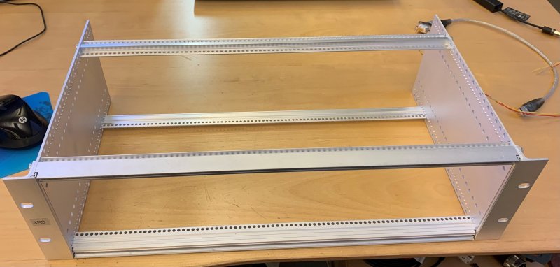
It starts with a “skeleton”. I found a suitable cabinet for the PA.
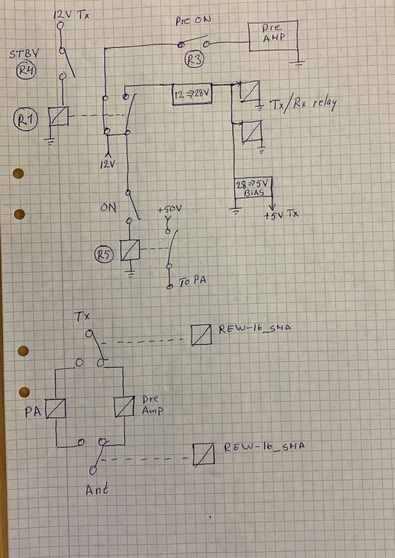
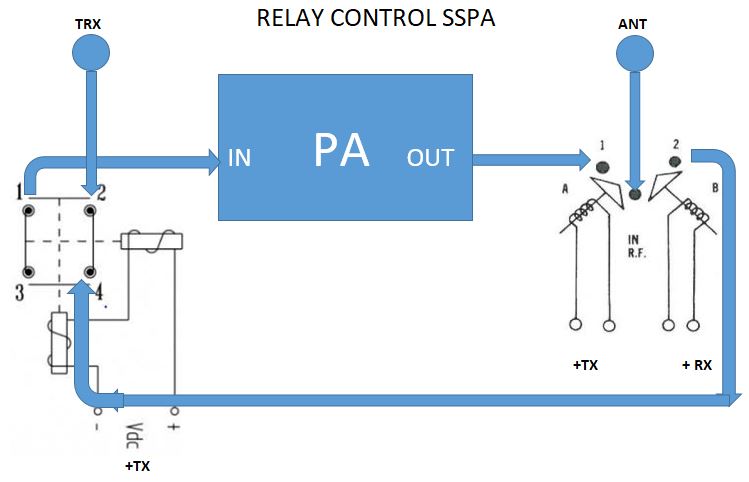
A simple schematic of the relay control. Nothing fancy at all, and now it is also different.
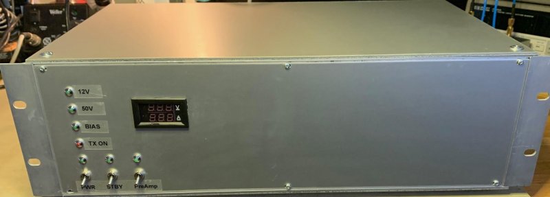
Some progress with the front plate. Current shunt in the middle. These cheap meters (DSN-VC288) does not like switched psu’s. Currently the current meter does not work. Again, cheap China products.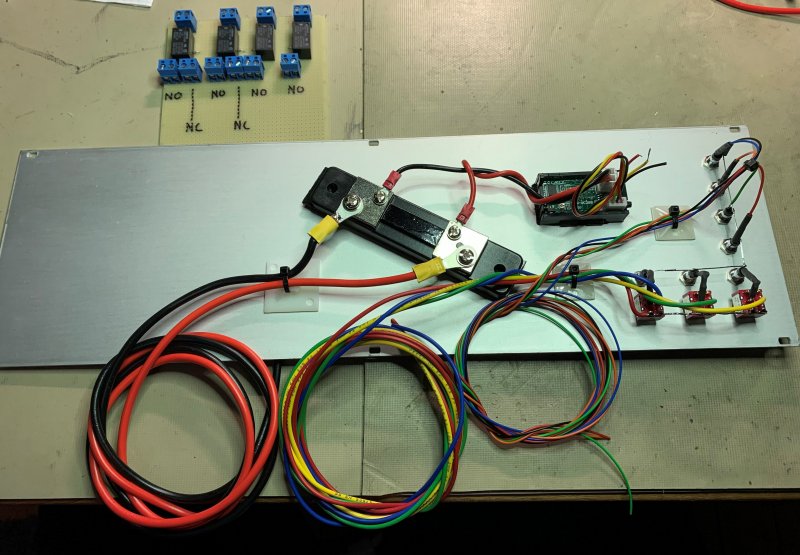
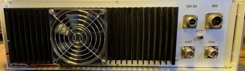
Back plate with mounted PA. The pcb is mounted on a cupper heat spreader then to a heat sink at the back. Much heat will be generated, and the aluminum heat sink is not so large which means that a fan will be necessarily. This was the” is it alive” test.
Yes it was alive for a while. But it also died. A small flash from the LDMOS, and then NIL.
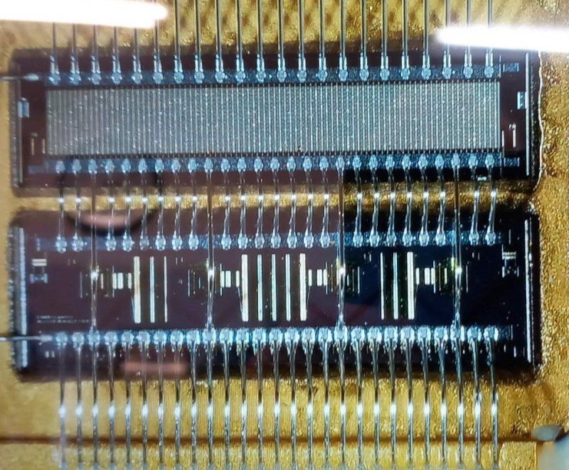
Fake, fake fake. Why? Why bother to manufacture these devices? This picture was send to NXP for examination. They came back and said that the left one was definitely a fake. The other would need more examination. The left one delivers about 40W maximum out, the right burnt off.
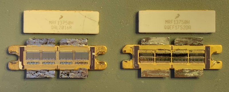
Zoom in on a real MRF1370.
So, more devices must be ordered. It takes a while for them to get here to Sweden. While waiting I started to test which relays to use in the amp.
Since I had a couple of relays at home I started to test them. EBay has sellers that promise relays which can handle high power and high frequencies. Well, let’s see.
This is a very simple test using 2 relays in a typical PA configuration. I will measure using a NanoVNA V2 Plus4.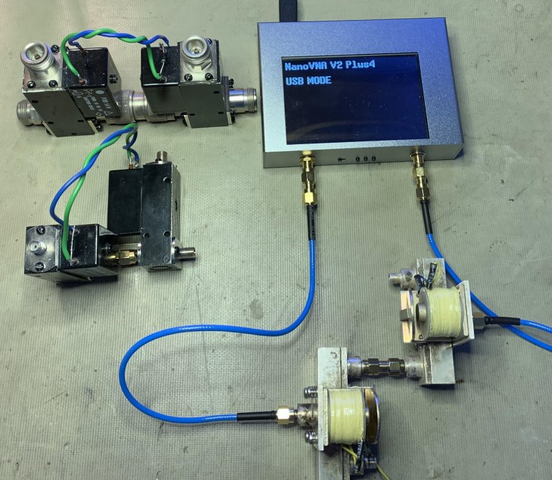
These are rebuilt relay without the Russian connector normally located on the REW-14/15. These are then called P3B 14N and P3B 16SMA.
P3B14N -2.7db @ 1296 Almost 50% loss in these relays.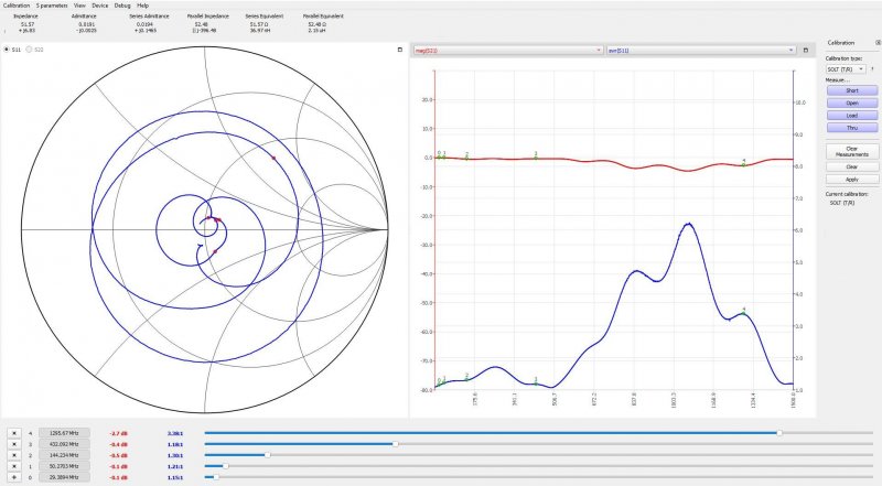
P3B16SMA -5.2db @ 1296 Terrible.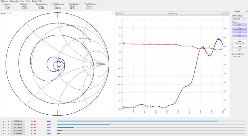
A transfer relay. RRTL-TN1A4 from RELCOMM. -0.5db @ 1296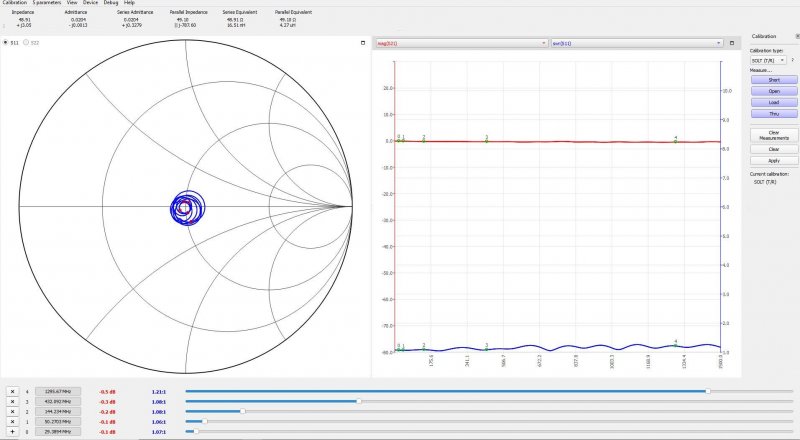
A couple old Amphenol with SMA connectors. -0.5db @ 1296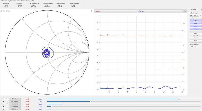
A Transco relay. -0.2db @ 1296. This will be added to the coax loss for TX.![]()
For the PA I will use a Transco relay together with the RELCOMM. This to protect the in/out of the PA so the 2 ports can never be connected.
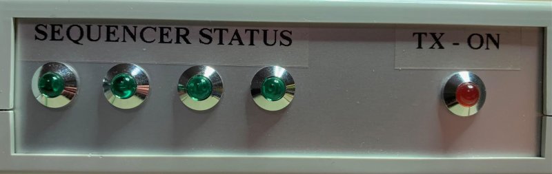
A simple sequencer was made using an Arduino Nano.
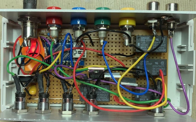
Looks like a mess inside, I know. First the Transco (PA out) relay switches. This also cut the 12V in the coax to the Pre-amp which goes to by-pass. Second the transfer relay (PA in) switches. And finally the bias turns on.
Some metal work done.
Inside view during a test-run.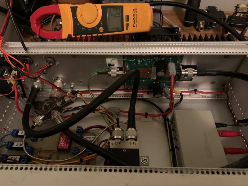
The output power from the IC-9700 is set in percentage. It does not necessarily mean that 10% is 1W 50% 5W etc. There are deviations, however it is quite close. I made a chart for % drive Vs power out. There are of course some losses between the 9700 and the PA input as well.
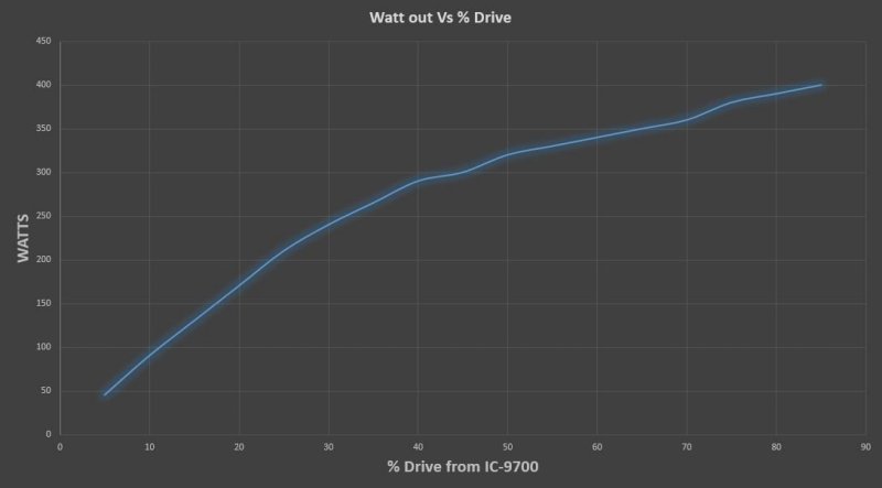
Anders gets 600W output with 12-15W drive. I have only tried up to 400W with 85% drive ≈8W, 17db gain.
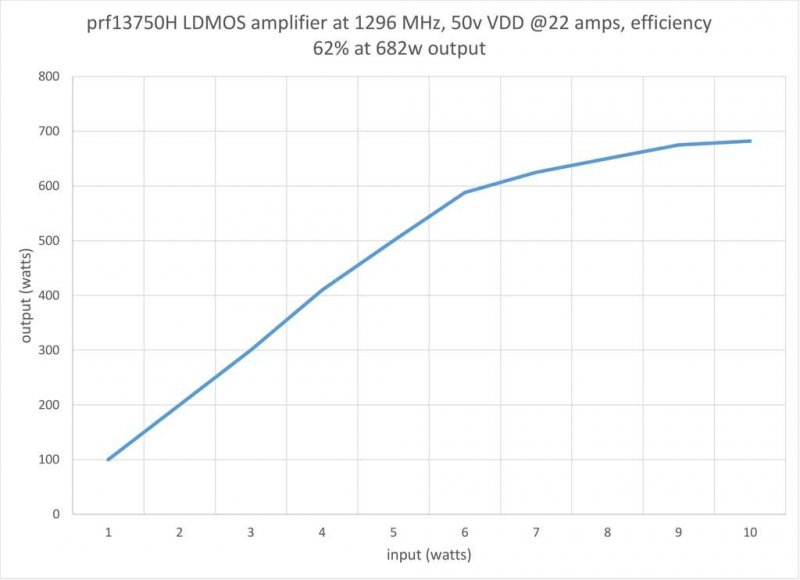
W6PQL made a graph of his amp. Seems he has higher gain, however I did not measure the actual rf in to the PA. There will be some SWR and % Vs W is not exact.
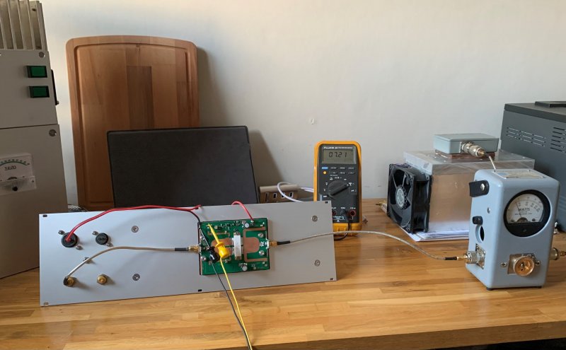
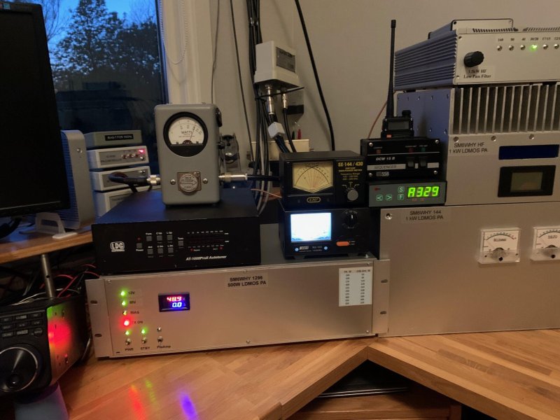
300W out, more or less finalized. To the right some other PA’s. HF and 2m, soon going to make a 70cm PA as well. Now done: 70cm UHF TV Amplifier | SM6WHY (n.nu)
Things that is good to have when soldering PCB/LDMOS. Ir-meter, fluss PTFE protecting sheets.
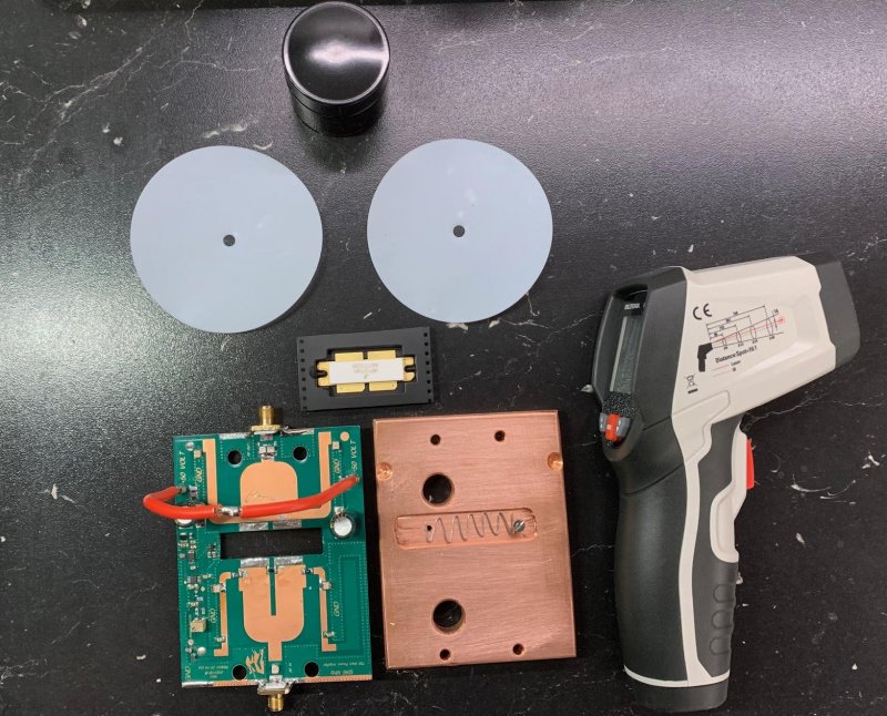
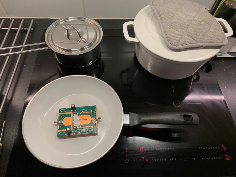
And, if don't have a small heating plate the kitchen will do. Ask XYL first.....I didn't.
Link to Anders: https://www.sm5dgx.se/
73 de SM6WHY
Lasse
Welcome
Welcome to sm6why.n.nu.

My Newsletter
Links