
70cm UHF TV Amplifier
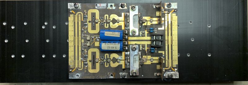
It seems that on 70cm it is easy to find a surplus amp. I found one with 2xBLF 861A which can deliver 250W out on 432MHz. I had a nice heat sink already.
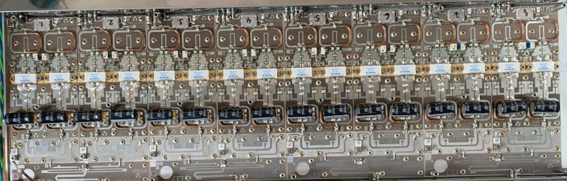
These modules are fitted in high power UHF band TV PA’s. Each PA consists of 64 water-cooled modules for 10kW out. Now they are replaced by low power DVBT2 transmitters.
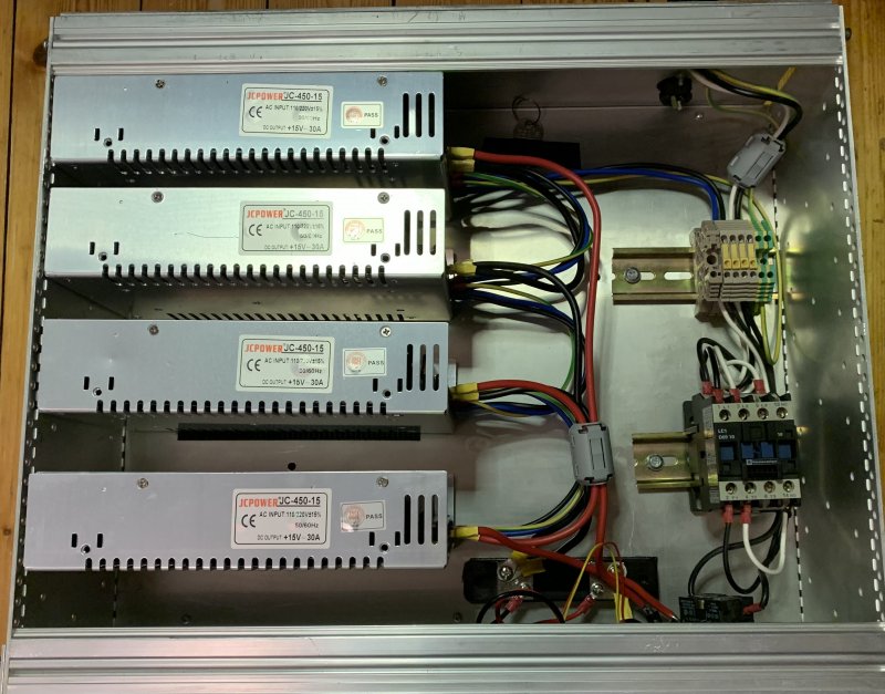
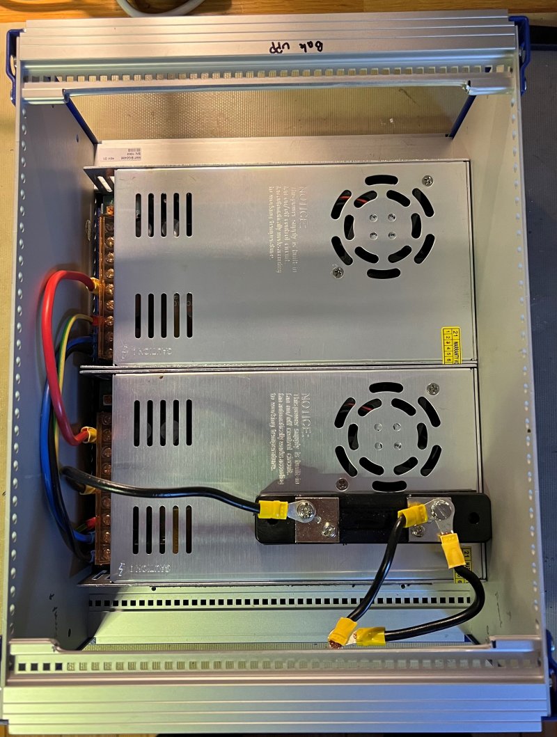
One thing needed is the PSU. 28-32V and quite a few Amps. Since I have a larger QRO TV amp as well I decided to make a 60A PSU.
I use 4x 15V 15A power supplies. 2 in series and then parallell coupled
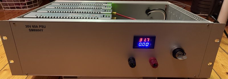
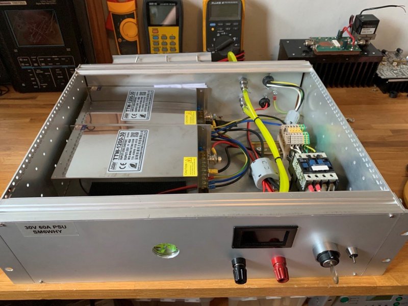
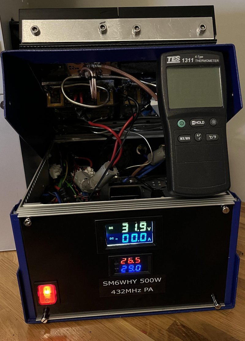
I rebuild this PSU to an 80A version, 2x 30V 40A. This one also has an “eye” to see that the water cooling works. It also controls the water-cooling pump and a Peltier cooler mounted at the back.
The reason for 80A was that I had a plan to get a kW TV amplifier on the air. However I had a lots of problems with that amp. Several of the Gold-Mos transistors did pop.
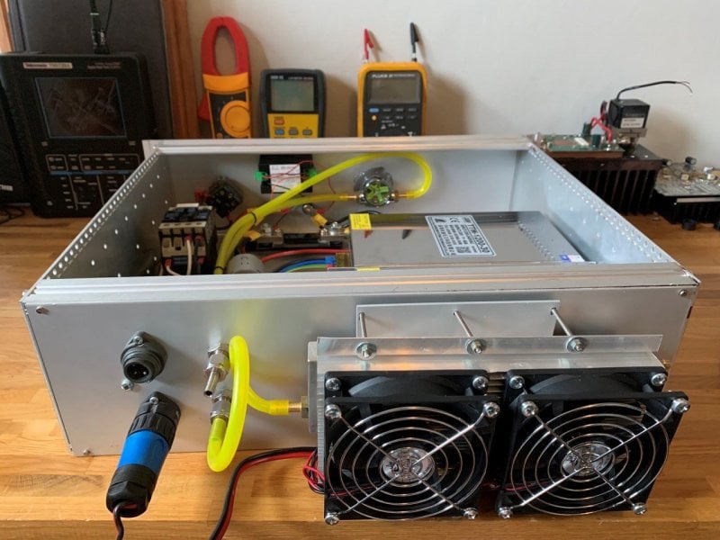
The kW PA. Maybe I will find motivation to finalize this PA. 8x250W (in theory).
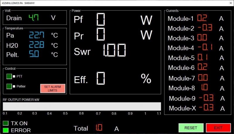
I made a software for monitoring and for security, if high SWR high current or output should occur the PA will shut down. The currents for all modules are monitored.
Anyway, the QRO PA is left for now, and now I will try to make a 500W PA with the other modules instead.
Initial PA test:
10dBm out from the 8656B was 11.7dBm on my SA including 2pcs 30cm RG-402.
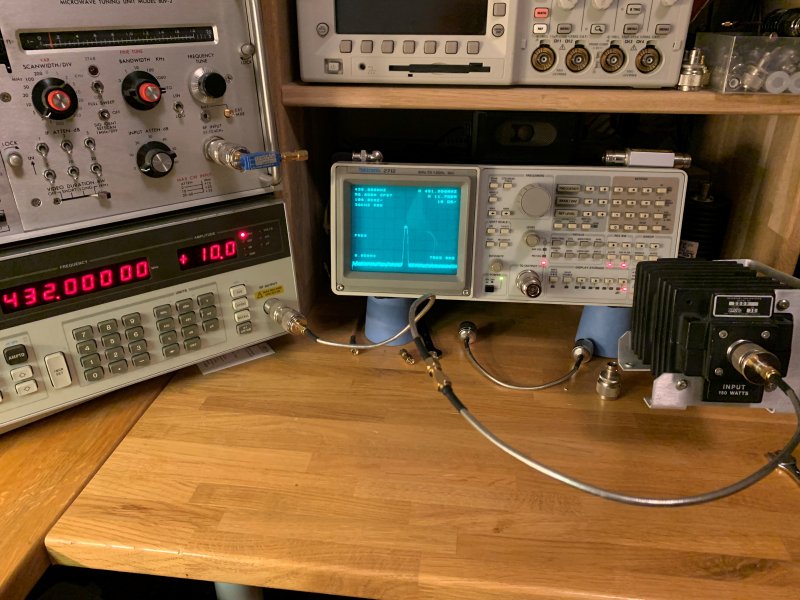
With 10dBm drive the output is 26.6 on the SA. -11.7 yelds about 15dB gain. Not bad.
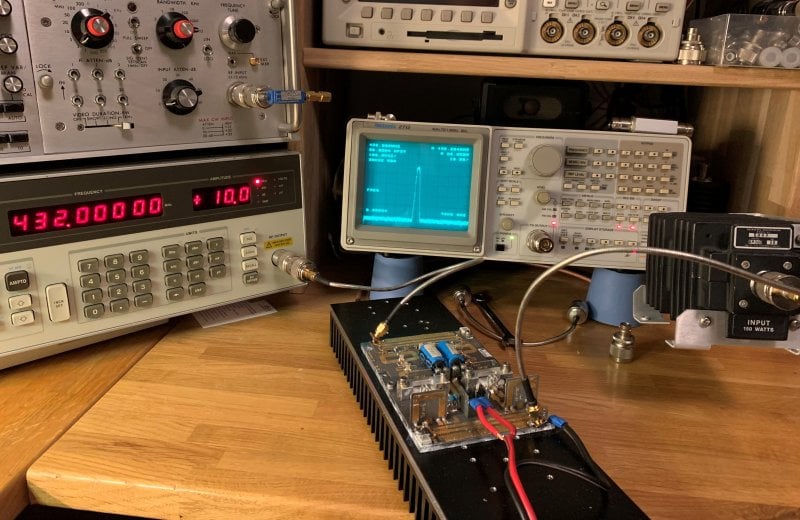
The module needs about 13W input for 250W out, @ about 32V and 14A. > 55% efficiency.
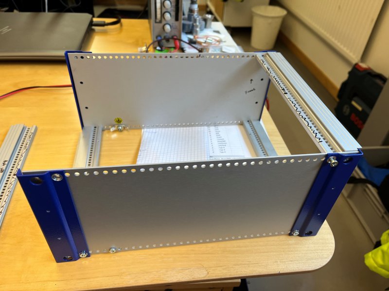
Absolutely nothing wrong with 250W out. However, 500W is better. This means that I need 2 modules and combiners. I started to make a cabinet that has the PSU inside which is 2x15V 15A each.
I started with one module; one more is ordered.
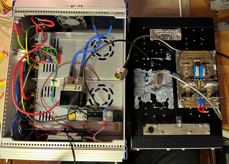
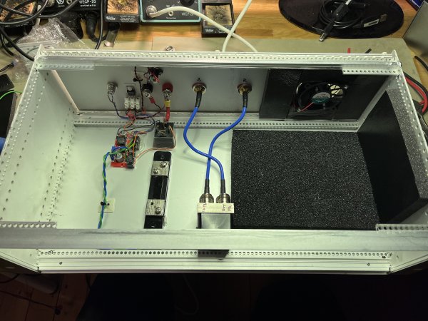
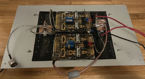
PA front:
PA back:
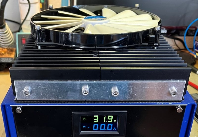
2 heatsinks are mounted together, and a 200mm fan is temperature controlled from the module at the front.
First real test was the NAC 432 test 2023-10-10, using 250W output. I used CW, SSB and FT-8 all reports was good. Good audio report from SM6VTZ in SSB mode, 59+. In FT-8 mode the PA was kept cool with the 200mm fan.
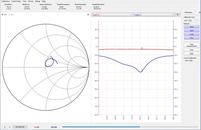
Next is to see if 2 modules will work well. 2 of the dividers were tested by connect them with short pieces of semi-rigid. The loss was -3dB. This is a very high loss. SM6VFZ, Daniel pointed out that the divider to the left is a Wilkinson with 0° phase shift. And the right combines with 90°phase shift. That's the reason.
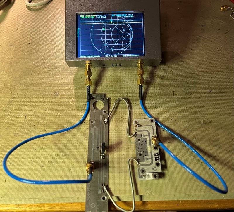
It is also possible to terminate one port with 50 Ohm and measure on the other. This will reveal the loss in a single divider. It seems to be -3dB again, meaning no loss.
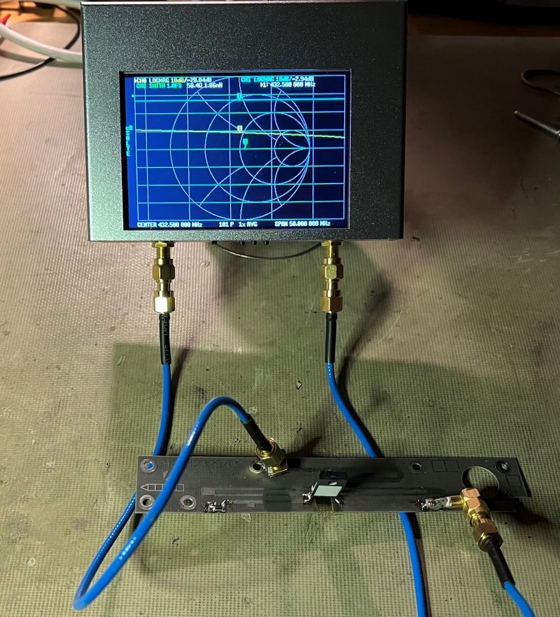
And the other Wilkinson divider. -3.2dB with the other port terminated.
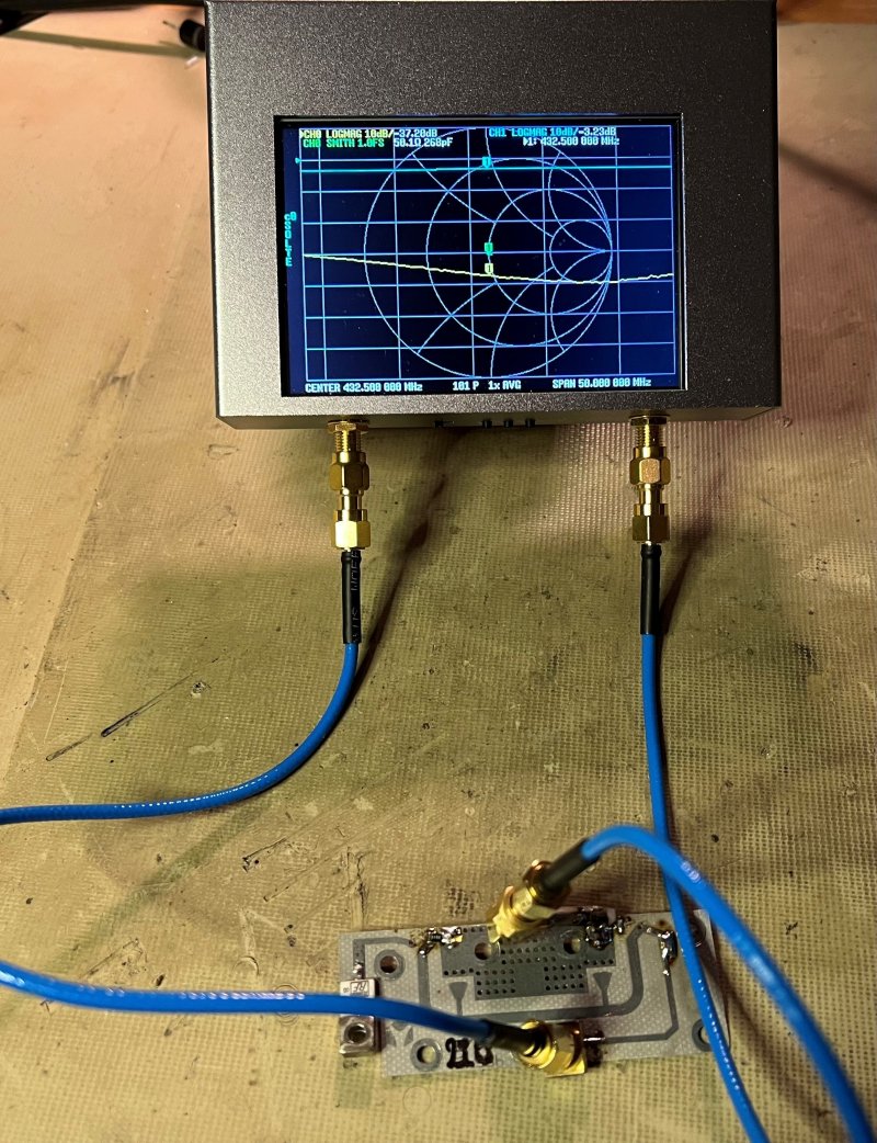
Since the actual range is 470-860MHz we can test a full sweep. Here 400 to 1000MHz using 1000 data points. Marker1 @ 432.4MHz -3.2dB. The divider has about -3dB loss allover it's range. >33dB return loss @ 432MHz. In this measurement -0.2dB actual loss.
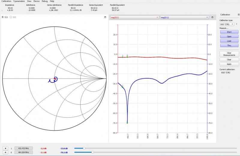
Well commercial wide band combiners/splitters works. However the Return Loss can be poor. I made a simple combiner of a 100Ohm 500W resistor and 2 pieces of RG-179. RG-179 is 75Ohm, requested for a Wilkinson combiner is 71Ohm. It will work as good with 75Ohm, but the calculation is a bit off. For 432MHz I came to the conclusion that 11.5cm length works good.
VF for RG-179 is about 0.695. 299.8/432.5 = 0.693M. 0.693*0.695=0.48M. 0.48/4=0.12M.
So, 12cm length and about 2*5mm for soldering means total 13cm length for 432.5MHz. To get it perfect some length adjustments is probably needed. (see above)
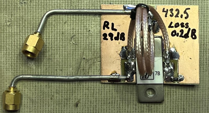
Not bad, 0.2dB loss and RL -29dB. It can handle 500W on 70cm, and has a low cost.
The bad in this story is that the dual amplifier has lot of problems in the small enclosure. When the top is closed the output decreases a lot. The current and Voltage readings becomes very nervous. In fact, there is too much RF in in enclosure then what it can take.
PA top open, 400W out.
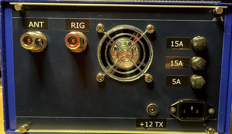
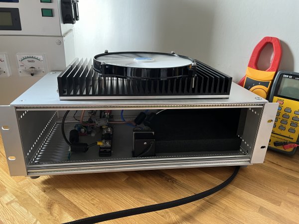
A new cabinet is needed for the PA. Luckily, I got one laying in the shack. Lots of space in this one. Added some foam to possibly damp oscillations., and it does also lower the noise from the fan. The internal fan will be controlled with a temperature controller, same as the one on the other enclosure.
A test run of the amp using homebrew combiners. Small video, 9187955872924555245.mp4 the range of the Bird-plug is 1kW. Meaning 500W out. I actually tested to over perform the PA and it delivers +600W out, however it would be quite stupid to run that as a normal condition.
Homebrew combiner/splitter for in/out. Low loss, good RL and very cheap.
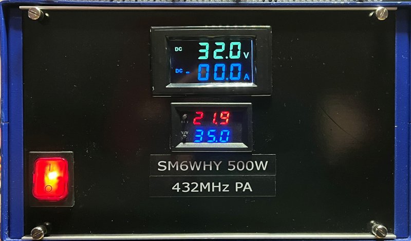
The PA so far, it needs some metering for V and A. A temperature controller will be added as well.
Now finalized and works good.
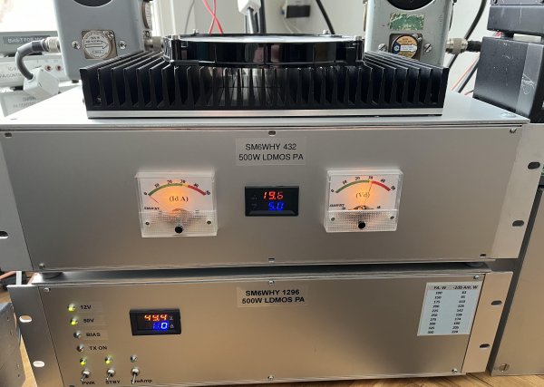
Link to the 1296 PA in the picture: Ldmos 23cm Pa | SM6WHY (n.nu)
Welcome
Welcome to sm6why.n.nu.

My Newsletter
Links