
Retro 23cm Qro
A while ago I came across of an old 23cm amp (from Göran SM6EDG). Originally these amps were called UPX-4. What I know is that it was used in a pulsed plate modulated L-band radar (900-1100 MHz).
Nowadays tubes are not really popular. LDMOS has taking over since many years, a MRF 13750 can deliver 600W out on 1296 with 10W drive.
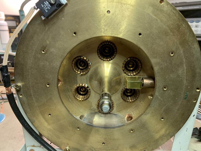
However, this amp is most likely made by Hans Rasmussen OZ9CR which made a couple of these modified UPX-4 style 6x2C39B tube amplifier. The amplifier is air cooled so a realistic maximum output is 500W. To minimize the expected thermal drift water cooling is probably needed. Another large benefit would be that the fan can be omitted. The output could maybe be increased to 1 kW. I heard that the old modified UPX-4 could deliver 500W out with 40-50% plate efficiency and a power gain of 10.
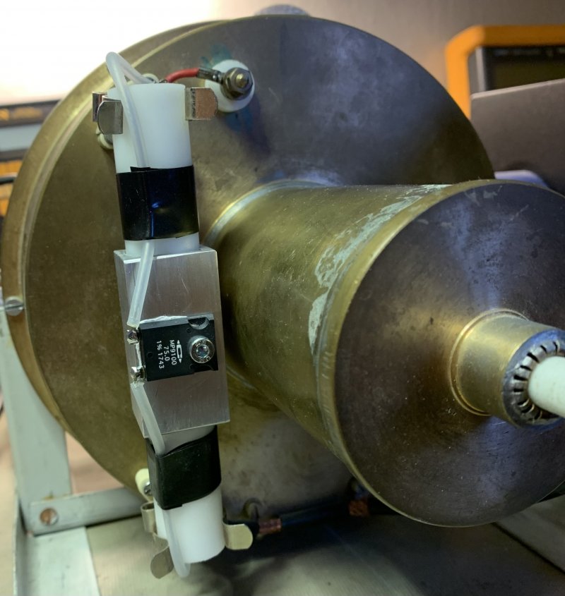
It is very clear that it is a big effort to build this amp. Therefore, I feel it is my duty to put it on air again. Building the PSU are not so trivial either. The none inductive 100W resistor is missing. I made one using a teflon rod and a 100W 75 Ohm resistor. This resistor limits the HV current if there will be an arc to earth and it also prevents eventually oscillation.
The "homebrew" glitch resistor replacement.
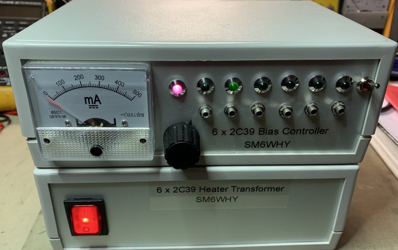
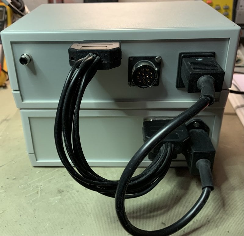
There was no PSU for this amp. 6V heater, bias and HV is necessarily. The heater and bias controller are built in 20x14cm size boxes. I used a toroid transformer and wired 6x6V windings. The bias controller makes it possible to have individual settings for the tubes. I will set the bias to 50mA / tube.
Each tube is selected by the rotary switch. To close the tube shut off relay the switch to the right is switched on, or if the RCA contact on the back is closed. The red LED means bias is on.
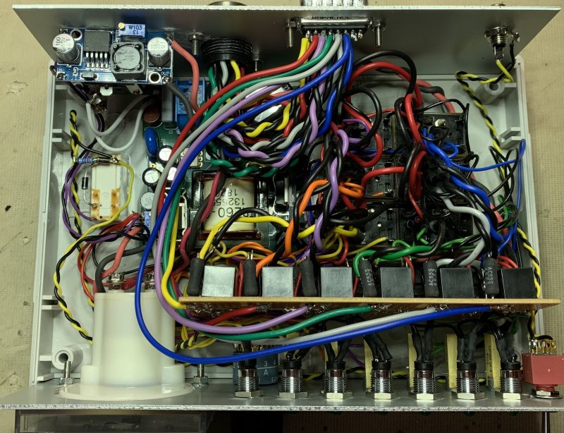
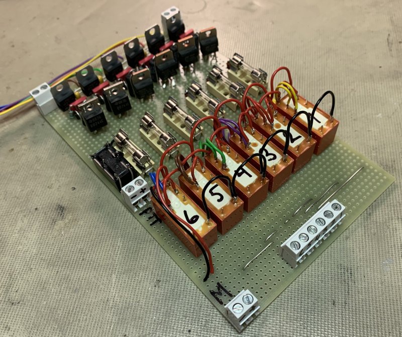
Inside is looking a bit chaotic. 13 relays are used and many interconnections. It can of course be better arranged, I just built it from head and realized it would not be easy to trace faults even for me. I made a small schematic what’s going on in the box.
A simple schematic of the bias controller. 6 of these needs to be made for the amplifier.
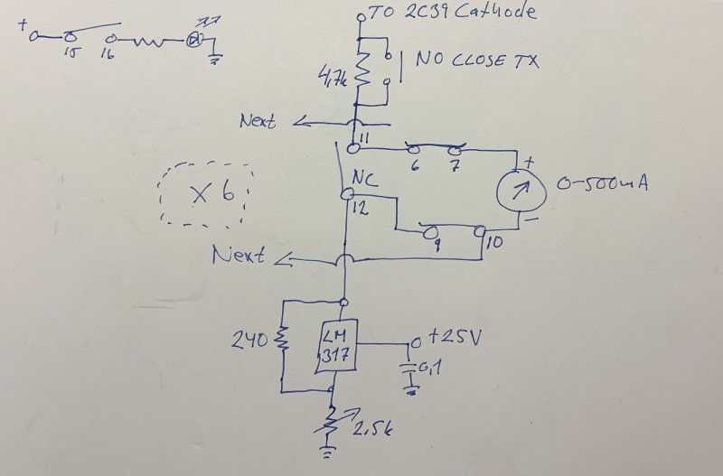
I did not have success with this bias board.
After talking to SM6ESG, Morgan which pointed out that the bias current to gnd will have problems. Thank you, Morgan for your input. Morgan has built a large amount of radio related things during many years from HF to GHz. I made a new board using N6CA circuit which has a PNP transistor to increase the current-handling. I also made the meter switching simpler and only use one 2-pole relay for each tube.
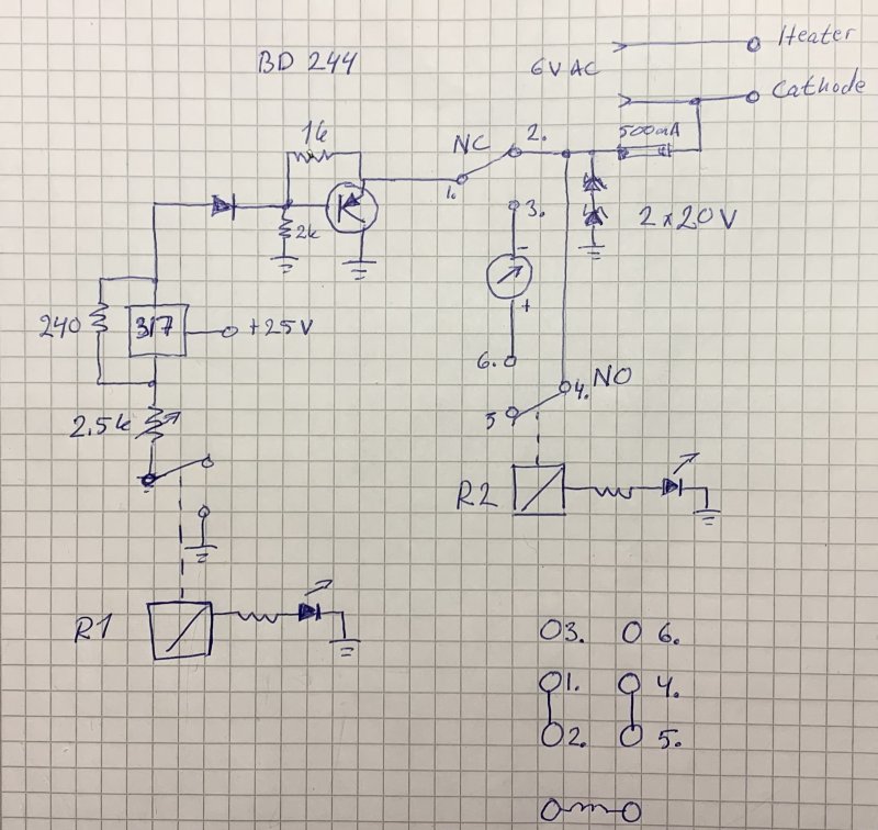
I’m not sure if the chaotic look is better in this new version, but it works.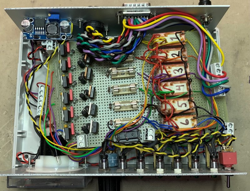
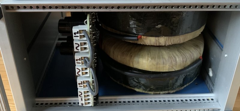
The HV is using 2 toroid transformers which has 3 x 290V windings each. By combing these windings 6 steps of HV can be selected. Means about 400VDC / step, 4 steps 1600V will probably be fine for this amplifier. As seen later 1.2kV is used.
I have built a small size HV triod psu before using a MOT transformer, however it has a fixed voltage of about 2600V, and it's way to high for the 2C39 tubes. https://sm6why.n.nu/hf-pa-gs31b
The rectifier board is built on a 100x160 glass fiber Veroboard. The rectifiers are rated 400V 4A, the capacitors are 400V 100uF.
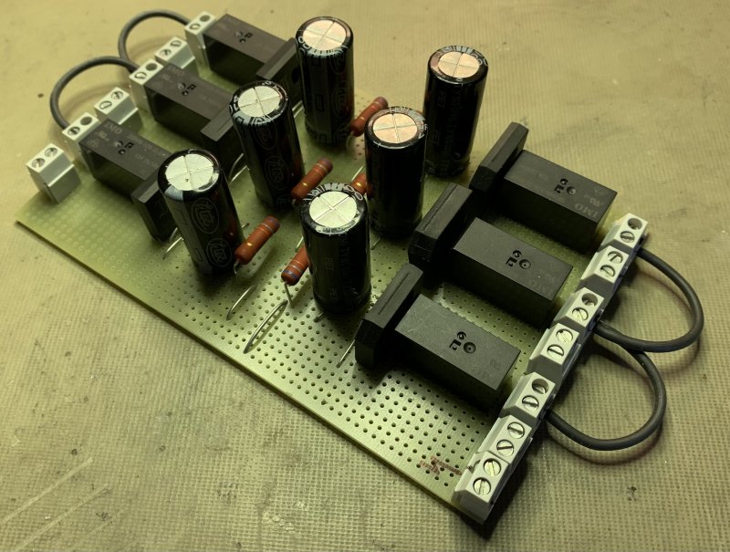
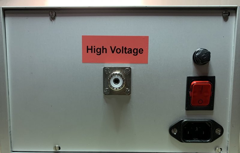
The HV box only measures 22x13 cm so it is very compact. This is possible because the size of the 2 toroid transformers is smaller than traditional HV transformers.
The HV transformers and rectifier board.
Back side.
First try-out test. https://youtu.be/LEdOKXfEIeY
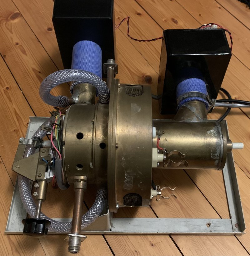
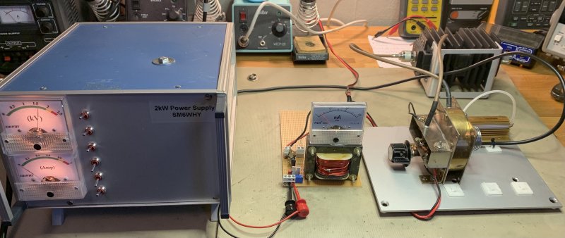
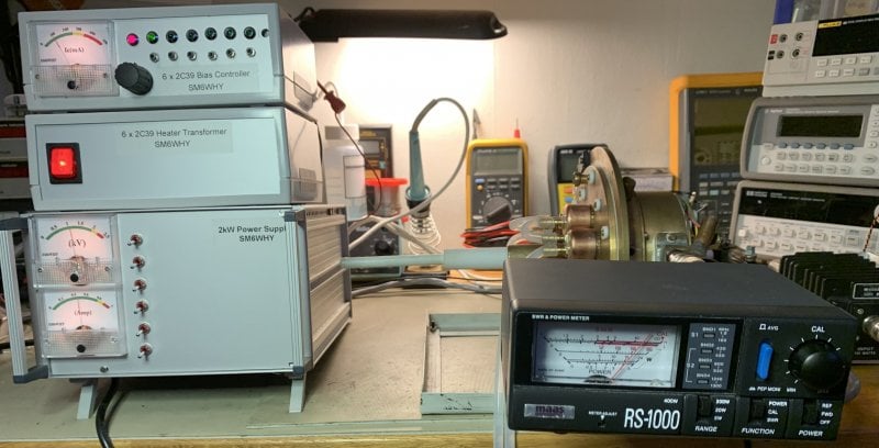
This is how the complete 6x2C39 psu looks like.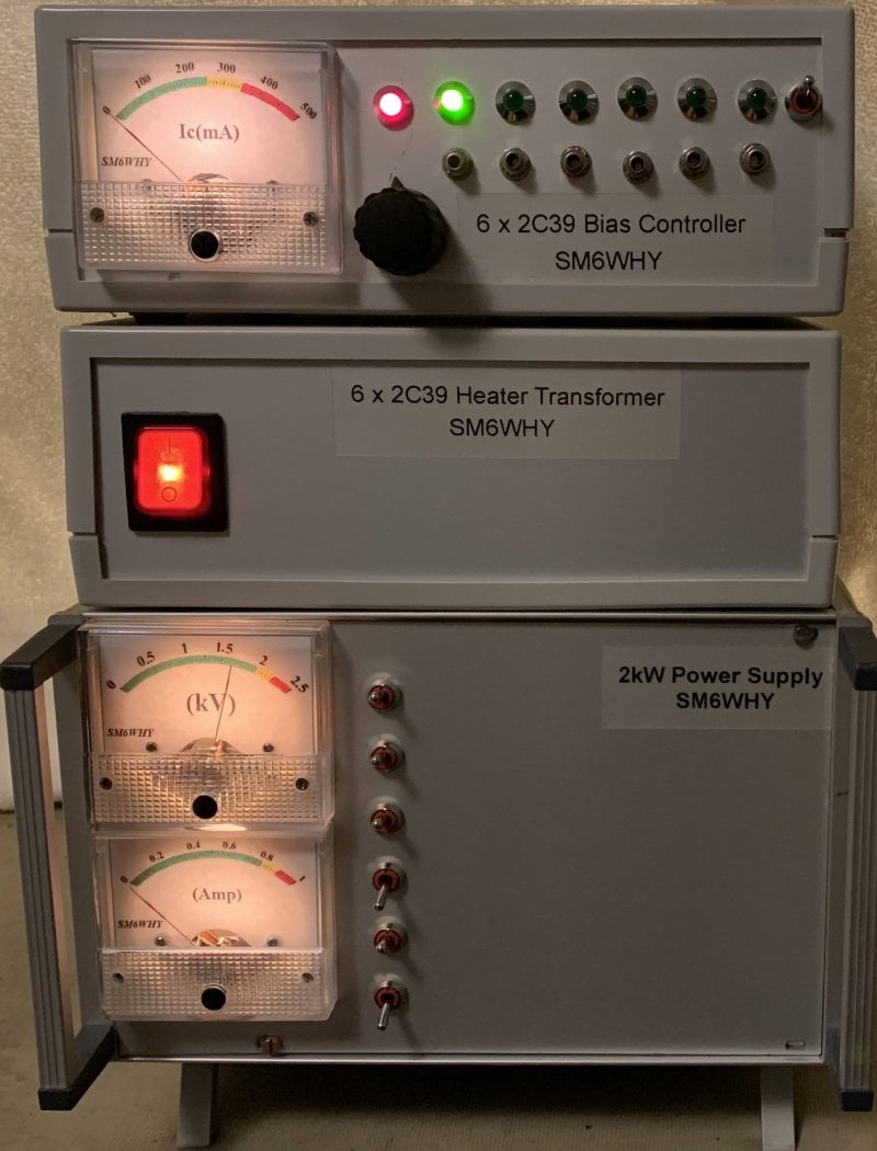
The HV psu did work, however during some load the Chinese 400V capacitors went up in smoke. Well, probably my own mistake buying cheap. Or was it my own design fault?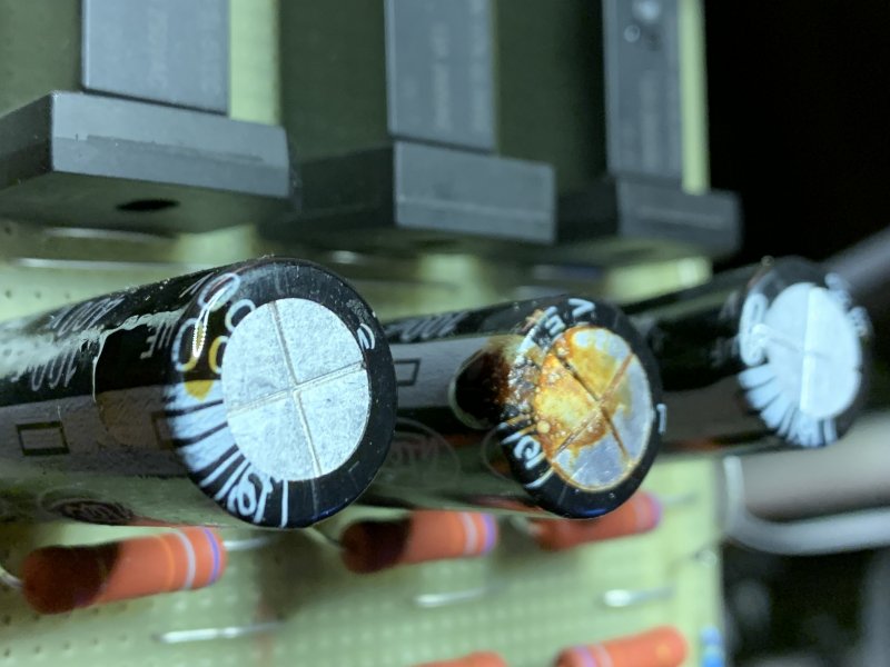
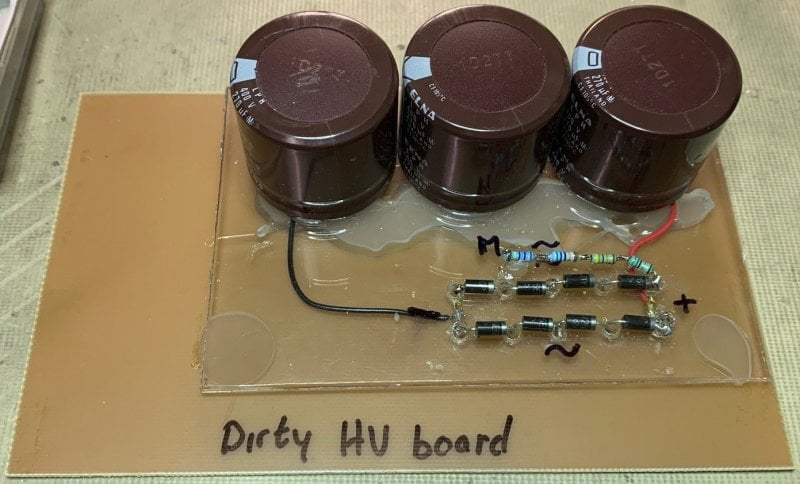
I will make a new quick and dirty HV rectifier board. I will also omit the possibility to select different voltages, even if that idea is great. I will have 2 Voltage options, 1.2 or 1.6kV. Many uses 1.4 to 1.6kV to keep the current down and increase gain. However, as Morgan said “increase drive and you get higher efficiency”. I will try 1.2kV and use 2 windings from one transformer and 1 from the other.
A very ugly board...but it is tested and works. The 100x160 copper clad board makes it possible to fit into the slit in the cabinet. Bleed resistors are mounted under the capacitors.
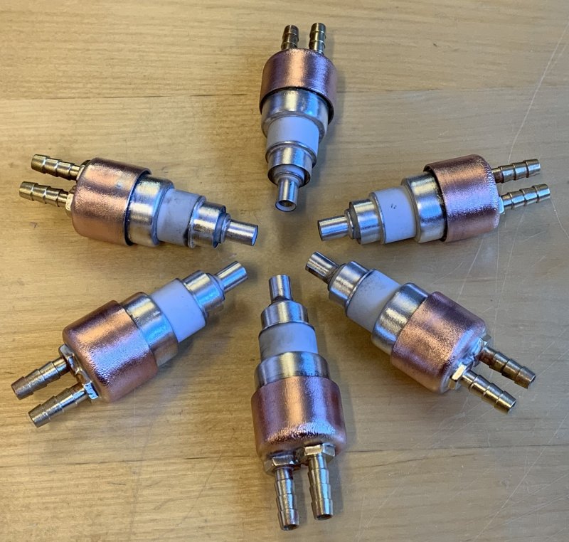
I have a couple of 2C39A and decided to make them water cooled. They need to be individually tested, I do not know their performance.
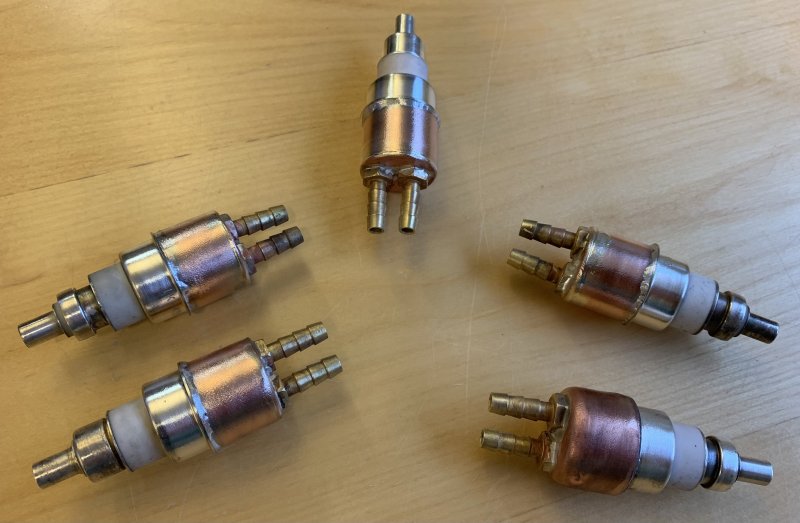
To be able to test the tubes individually I will use my 1 tube cavity. Some work needs to be done. I will use the same PSU as for the 6x2C39. Maybe I will put this amp in a box and use it as is...
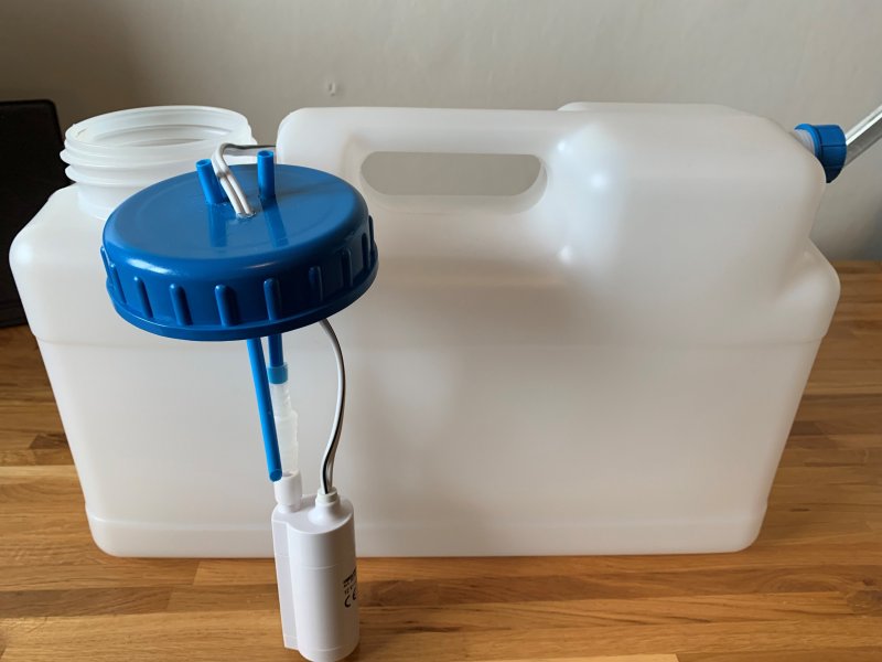
The pump I used for the water cooling is a diaphragm type pump. It did not perform so well. That one is mainly used for gas sampling. I made a new water-cooling system. It uses a submersible galley pump and a new 12L tank. The capacity is 450L/h and seems to work well.
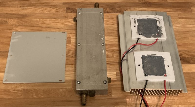
This works well for a single (maybe dual) tube however, I noticed that the water becomes Luke warm after a while with only 150W out. The efficiency is about 50%, so 150W needs to go into the tank.
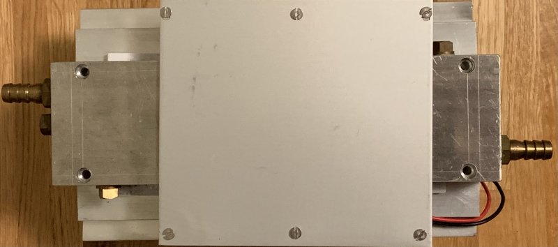
I made a TEC cooler, and hopefully is the size enough to cool down the water.
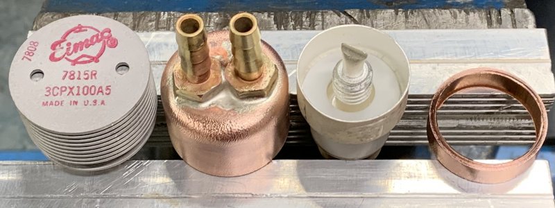
I also have a couple of NOS 3CPX100A5 tubes. I will need to have them with heater on for some hours and then test them with HV and bias on. I will modify them as well to be water cooled. They could be great for this amp.
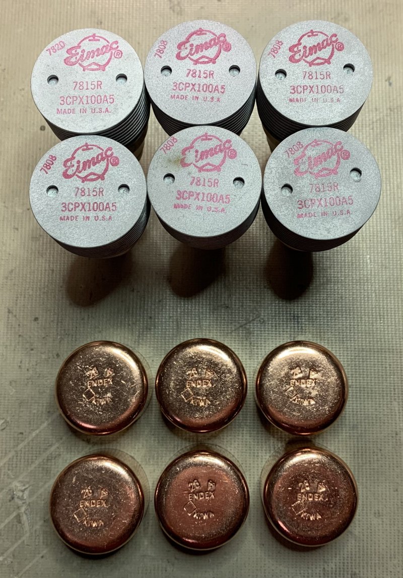
The 7815 or 3CPX100A5 is a ruggedized version of the 2C39 with ceramic body. Intended for pulse operations in Airborne DME or TACAN transponders. It has a longer grid-anode ceramic insulator making the tube useful for high altitude operations. Nominal plate dissipation is 100W air cooled. Usable up to 3GHz.
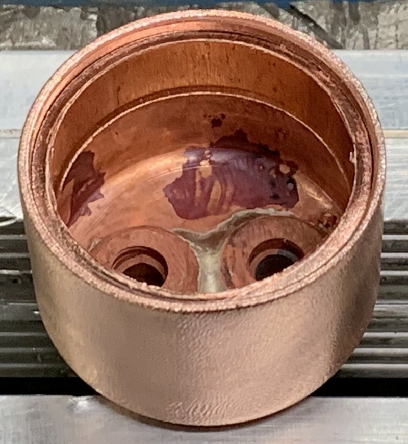
The 3CPX100A5 is missing the flange at the anode that the 2C39 has. This means the the standard 28 mm blind caps I used for 2C39 tubes will be a bit to large. I needed to insert a 5mm piece of copper pipe to make it possible to weld the tubes.
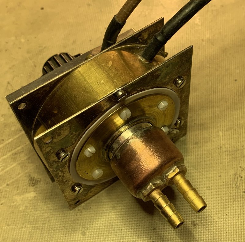
I tested the N6CA bias circuit on my one tube cavity before I built the new one, and it seems to work well.
Now the PA is water cooled.
This is just an initial test to show the PA potential. 7W in and 160 out, about 13db gain. Without a drive PA 200W out seems resonable. 100W from each tube is probably no problem at all. However my HV PSU will manage max. 2kW input.
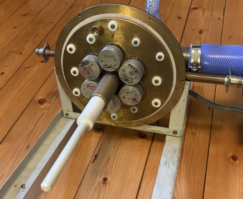
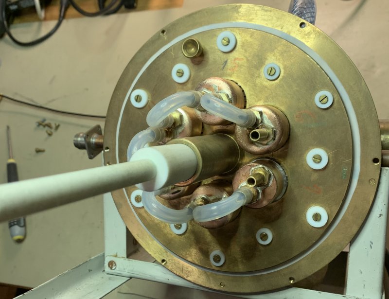
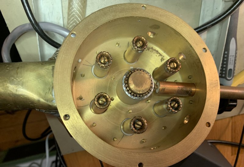
I needed to re-solder and re-adjust the in/output couplers in the PA.
Input and output sections.
The reason for 7W is that the rig is 2m from the PA and is feed by 2m Rg-58 and the loss is abot 3W.
A small video tells more....https://youtu.be/qDzdF8xftOA
Well, the amp works and I have put it on air. However the amp started to oscillate and generated a quite large signal. The input on my IC-9700 was burnt away.
I will see this as a potential PA that could be a nice partner in the schack. However I do not dare to take the risk to blow up my rig again right now.
It seems safer to go with one tube water cooled PA :)

Welcome
Welcome to sm6why.n.nu.

My Newsletter
Links