
Hf Pa Gs31b
I had a GS-31b laying around waiting for my urge to build another amp. However, this time I want to try a little different approach. Why not build a monitoring system that can be viewed from a laptop and the band switch could also be controlled from the gui?
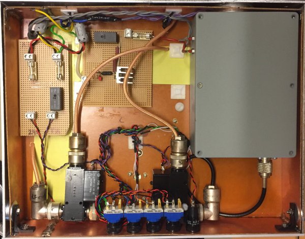
A new update to this is that the small I/O burnt up probably because high common mode currents generated from the 24V windings I made on the HV transformer. Bad luck, I have removed the I/O and control board and installed manual buttons.
More than a kW makes no sense for me. Think about it this way; 500W to 1kW is 3dB and 3dB is a half S-unit. Thinking of the sense of building a PA with these arguments makes really no sense, but building a PA is fun. A good antenna is of course essential for good communication.
Some say "life is too short for QRP" you tell me...
The triode is great of many reasons some are:
- Simple PSU
- The input/output is 180deg of phase
- Simple to operate
The PSU
First thing is to make a HV PSU. I made one from an old micro oven transformer. Micro oven transformers has a mechanical shunt that will lower the magnetic field if the power goes up. Remove the metal plates between the windings then you will have full power. They are often rated 0.7A 2.3kV. If you want more power, connect 2 in parallel, or as push pull. They are almost free. 15 to 1600W from this transformer will be fine and for IVS work (Intermittent Voice Service) like SSB it is enough with the half power of a commercial marking. W6SAI has found the values below regarding the weight of the transformer this table is from WB0NNI page:
TRANSFORMER WEIGHT - POUNDS
| Power Rating (KW) Service |
.1 | .2 | .4 | .6 | .8 | 1.0 | 1.2 | 1.4 | 1.6 | 1.8 | 2.0 |
| Commercial CW IVS IVS Min. |
4.8 4.7 4.7 4.6 |
12 8 7.5 6 |
17.5 11 10 8 |
25 14 12.5 9.8 |
32.5 17 15.5 12 |
39 21.5 18 13 |
47 24.5 21.5 15 |
- 27.5 23.5 17 |
- 32 27 19 |
- 34 29 21 |
- 37.5 32.5 22.5 |
Mine weights about 22 lbs. As seen about 1.5kW can be achieved with this transformer using SSB. IVS Min = 25% duty and IVS = 50%.
Compleated HV PSU.
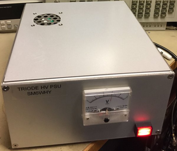
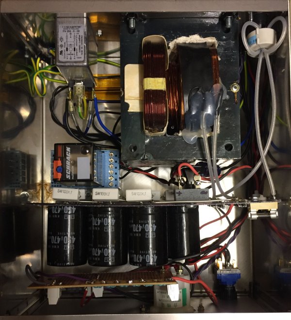
The relay and power resistor is a simple soft start. This will prevent high current rush into the circuit. I use BYV26EGP avalanche diodes they are rated 1kV 1A.
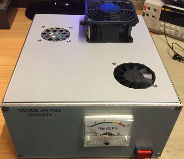
3 fan's is mounted for heat dissipation. The small fans are running constant and the larger one only at TX, meaning HV on. The PA's TX control now also control when the MOT has 230V. The soft start will prevent high current rush every time TX is enabled. Since a MOT always draws some current will heat be generated even at standby, therefore is this solution preferable when using MOT's as HV transformers.
This small HV-supply is actually great for many medium power amplifier. My GS-31 PA can deliver about 600W CW output. Of course is this not so much from this tube, but 2 GI-7b can use this supply.
New update. I re-tuned the amp and now I can get 1100W out on 40m!
https://www.youtube.com/watch?v=madFJJi-YVM&feature=youtu.be
New HV supply for this amp sm6why.n.nu/HV-on-wheel
The PA
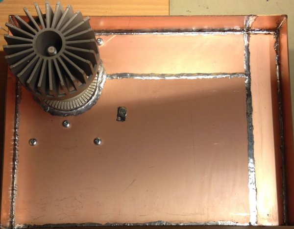
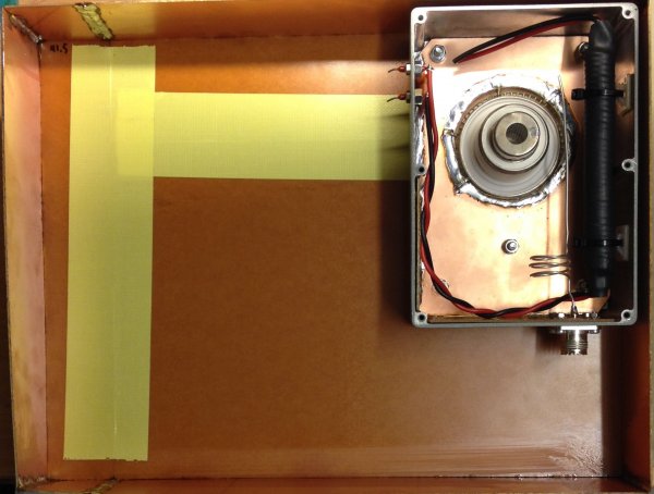
A simple way for me was to make a frame of copper clad boards. I do not know if I'm the first one but I have not seen this before :) I used finger stock for the grid.
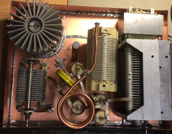
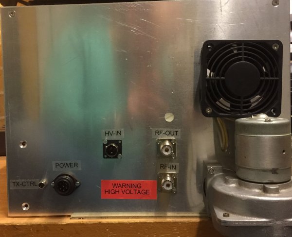
Update on the RF deck...
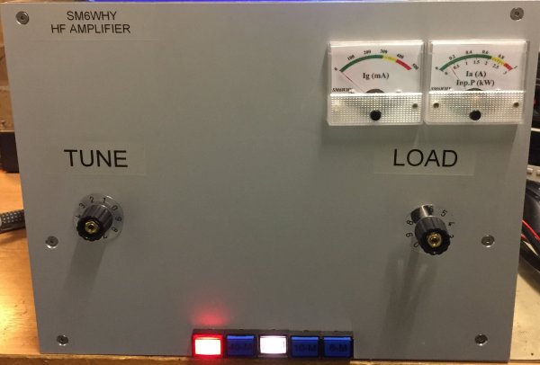
Current status of the "control deck"..Only manual switching possible.
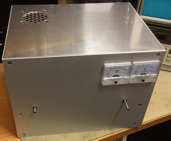
Some hardware work done...
A test on 20M into a dummy load. 20W in and 425W out. Still waiting for new control knobs. Now only manual band selection is possible.
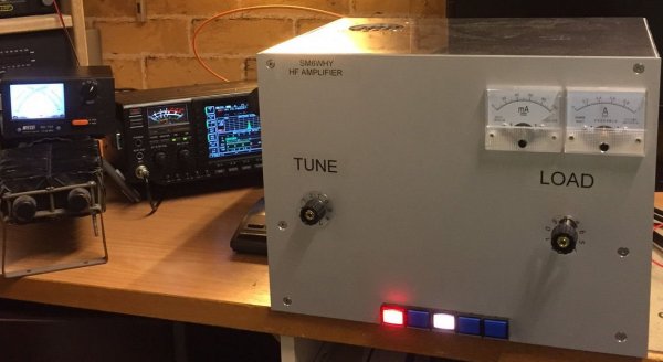
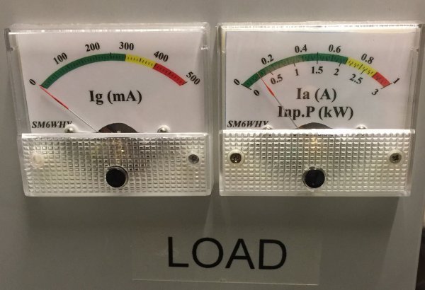
I made new scales to the meters...here in idle mode. Using the progam Galva by F5BU.
The amp also needed more cooling, one more fan installed. The chimney is shortened and the fan can blow direct to the anode cooler. The other fan is cooling the cathode and up to the chimney.
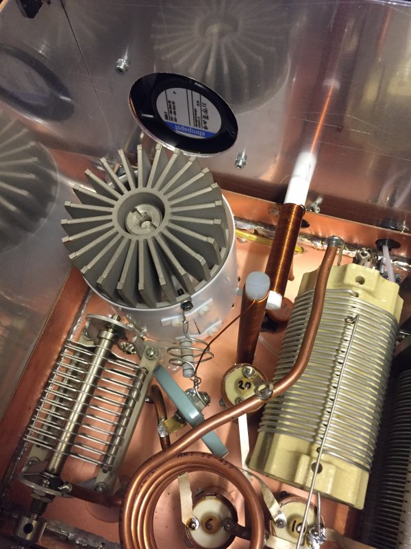
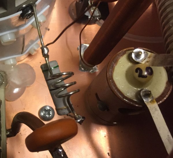
As seen above the blocking cap is close to the coil. It is a large doorknob style from Russia. There was an arc between the cap and the coil. The HV fuse triggered and it seems like the tube was all right, after all. However I changed the cap to another 2200pF 6.3kV. Do not want to risk this again. The parasitic choke where replaced by one made in stainless steel. It seems to be a good compromise.
So far..
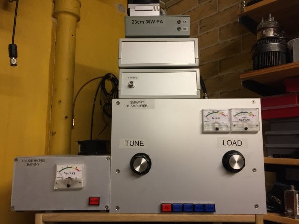
Here in live action...
https://www.youtube.com/watch?v=madFJJi-YVM&feature=youtu.be
Welcome
Welcome to sm6why.n.nu.

My Newsletter
Links