
Anritsu MS710
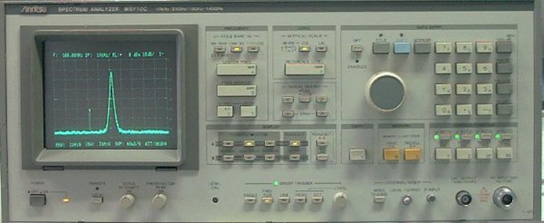
I came across an Anritsu-MS710A spectrum analyzer, the status was quite poor. 1st was the pre-selector removed, which I found out after opened the unit. And the input attenuator failed on several steps. I did find a unit on eBay that had a broken display, it was not really super cheap, however I hoped that a spare unit could be the solution for one working unit.
The complete input unit was taken out from the spare unit and replaced the "original" one. A test run showed that the attenuator had the same problem. It seems like this is a common issue with these units. But now the pre-selector did work!
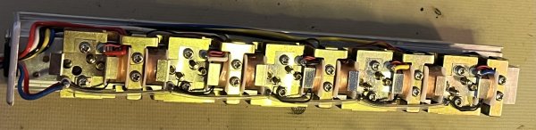
I removed the input attenuator and tested it on the bench. On/off is selected by reverse polarization of each coil. One common lead to all relays.
Ok, so how to solve this?
It is of course possible to use fixed external attenuators and by-pass this internal attenuator. However I did find out that if the short switching pulses was made longer (manually) the attenuator did work and switched properly.
Extremely simple and ugly schematic:
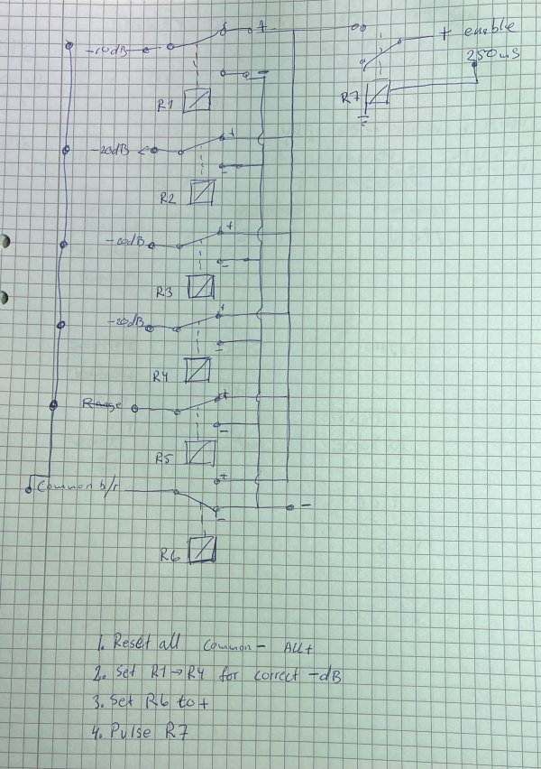
A pulse of 250mS was tested, sometimes this was not enough. 350mS works for now.
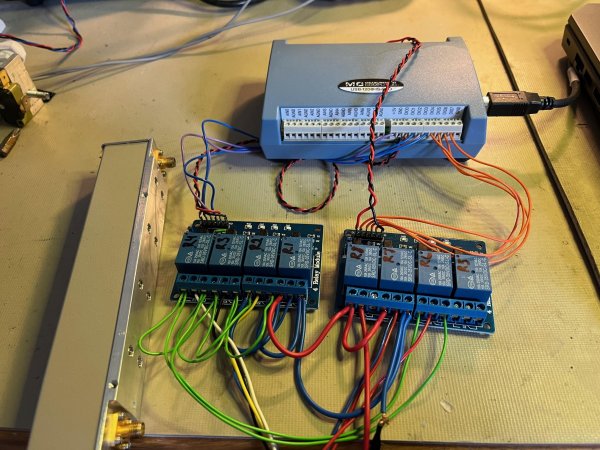
I had 2 choices as controller, AVR or PC. I made the PC choice because I had a small left over I/O. If I did not already have this, I would of course chosen the AVR. This I/O is not cheap, and maybe I will make the attenuator complete stand alone.
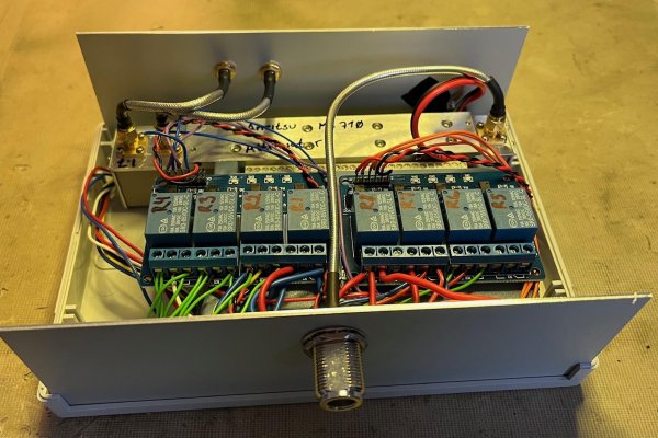
Here a test run on the bench, cheap Chinese relay modules used.
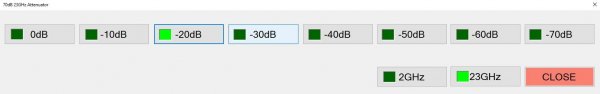
The PC program is written in VB.Net. The GUI is not fancy but does what it needs.
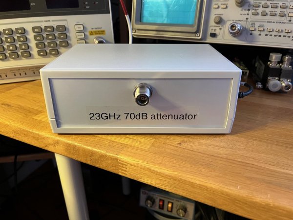
Everything was mounted in a box.
Now the unit need to be amplitude calibrated. Normally I use my ADF-5355 as signal source, however there are problem with this. When I set the 5355 to generate 10.368GHz I set the fundamental to 2592 MHz. When this is connected to my HP432A power meter it reads -5dBm. But, this is the sum of 2592, 5184 and 10.368. Therefore I needed another signal source.
On eBay cheap 10GHz VCO's can be found FVC99. Thank's Daniel SM6VFZ for the tip.
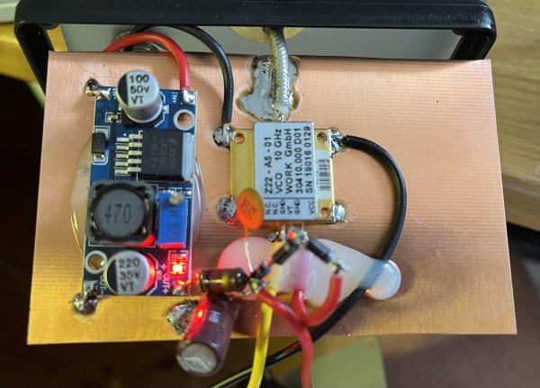
Built in a box and a test run.
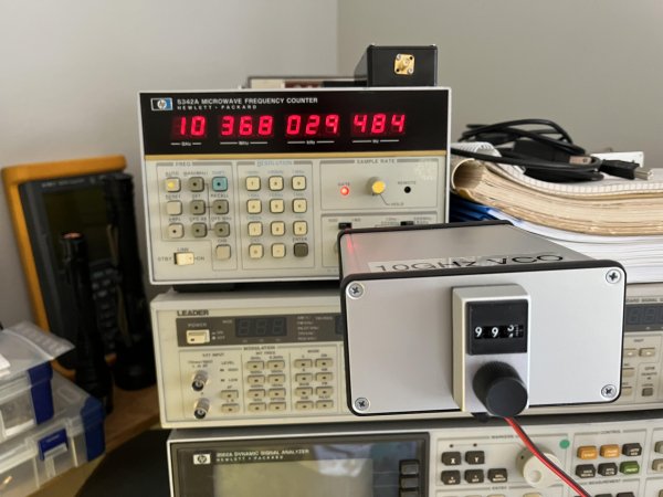
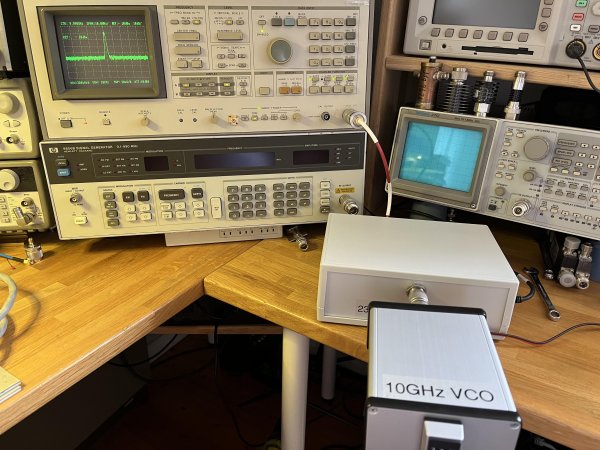
It works, but the output level is only -7dBm. It should be about 2dBm. As seen from the picture above I use a N chassis mount cable connected to the VCO. And measured with the HP 432A. I decided to replace the Chinese N-cable to a Suhner cable. And voila, 2dBm out. Sound crazy, I know.
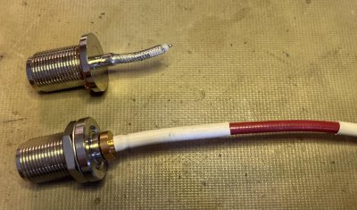
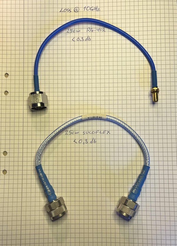
But the SA amplitude could not be adjusted to +2dBm. Guess why? Look which cables I used inside the attenuator. A bit disappointed I decided to test the cables I have.
This is just a simple loss test I made. See the loss for the female N!!
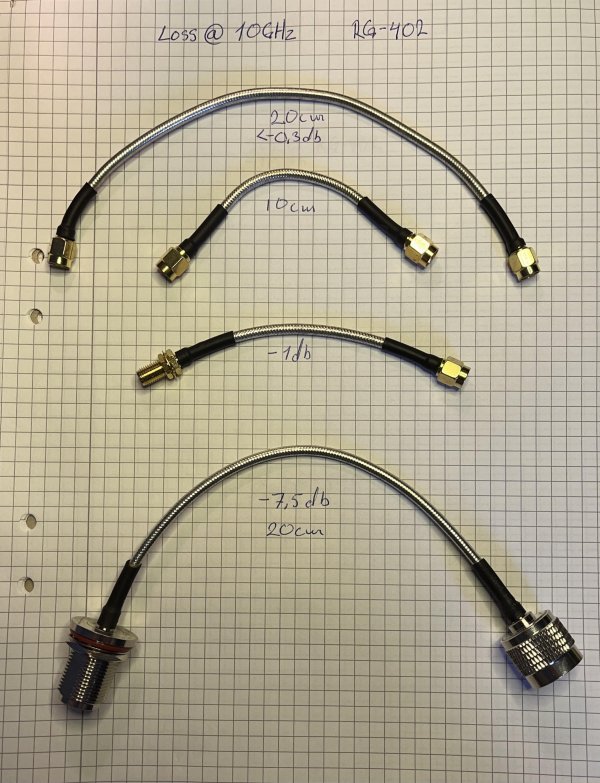
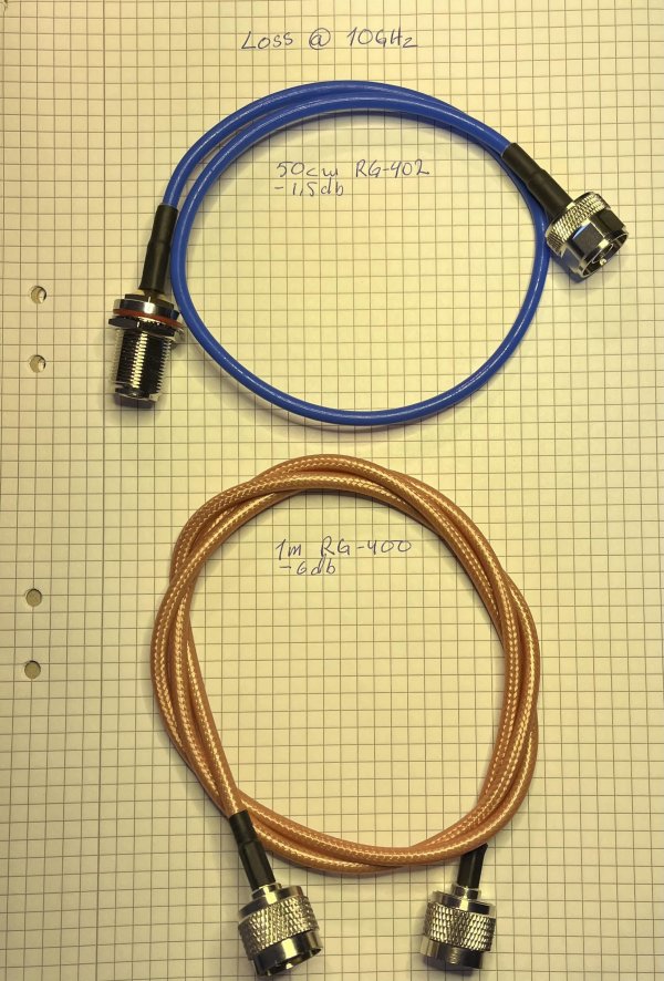
The useless (on 10GHz) Chinese N-cables was replaced in the attenuator, and the amplitude could be set to 2dBM.
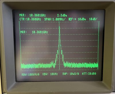
This also revealed that the ADF-5355 level on 10.368 is -13dBm.
Welcome
Welcome to sm6why.n.nu.

My Newsletter
Links