
6cm Project
So, time to try to realize a new project. I have done the 3cm project and it is working. From my QTH it is quite hard to get long distance contacts. SM7ECM is 222km away, and is about the distance for 10GHz I make at the most. Some of the Danish amateurs has also been worked. That said, the cost / QSO is high. Transverter, PA and parabola cost.
6cm is even less to work here. I doubt I will hear many stations. BUT I want to try.
SM6VFZ is an old radio amateur friend (he is not old), he is a very good RF-designer. He has written in DUBUS magazine many times, and he also work in the RF industry. He had an idea of building a 6cm transverter. It is not (as for now) an available kit. But I have the possibility to try to put things together. He made it easy for me to get started.
So, LO, mixer, front-end and PA is needed. My IC-9700 is my IF working at 144MHz. To lower the IF images 432MHz could have been used as well.
Daniel has constructed a very versatile LO board. This board is now locked to 2808MHz. To be able to use it on 6cm the LO needs to be doubled. It is possible to use a frequency doubler to generate the needed 5616MHz for 144 IF, and then a suitable mixer.
Daniel preferer’s a sub-harmonic mixer. I have not made one before, so let’s try.
The schematic of the sub-harmonic mixer:
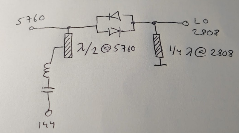
144.4MHz resonate frequency yields 100pF and 12.15nH inductor. The inductor can be made 2 turns 6mm diameter 9mm long.
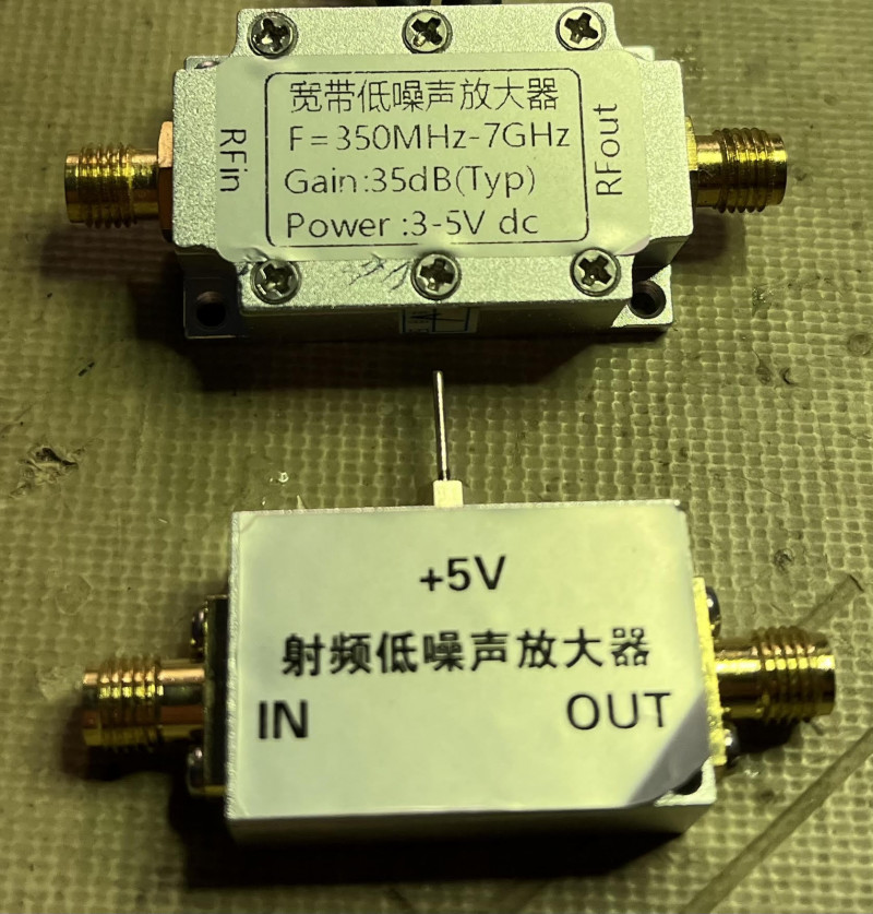
If the mixer is constructed well, it can be very efficient. I used RO587 0.8mm laminate, which is low loss. However, my layout is very basic. The losses in my mixer are about 15dB. But my parashoot in this is my small Chinese LNA. Despite the loss I can add gain and move on. Of course, would a perfect mixer be better.
This means that I could go only with Chinese LNA’s and omit Daniels front-end and only use the 2808 LO. But his front-end is very nice, and has a nice low noise figure. One of the Chinese LNA’s in the picture has a NF < 1 dB. For my 6cm work that will do.
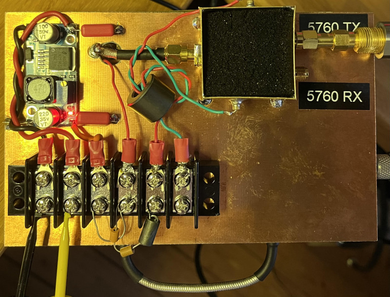
I have mounted the basic set on a double-sided PCB board. I made a double 5760MHz BPF of plumbing cups. The filter work well. The loss @ 5760 is about -2dB.
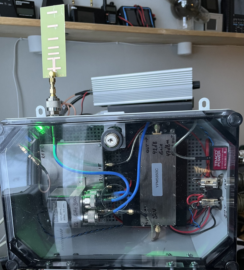
LO, sub-harmonic mixer and filter on this side:
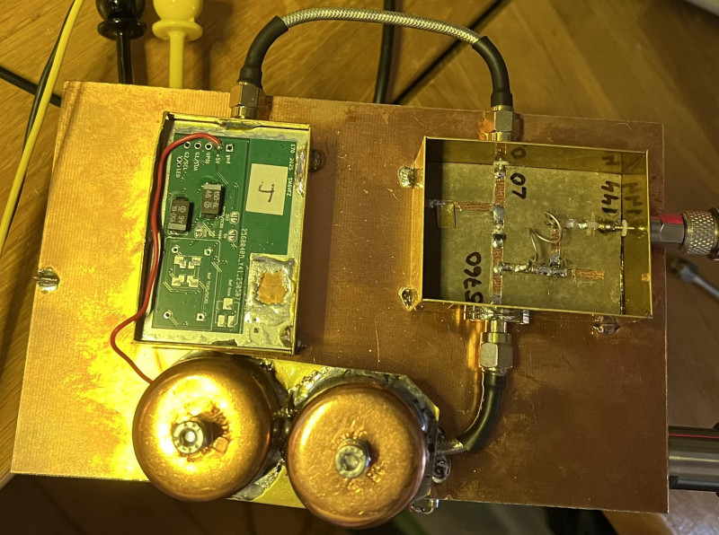
The other side consists of the RX/TX front end and a dc-dc step-down module.
With everything connected have 0dBm IF in and 2dBm 5760 out. IF rejection is about -30dB.
I guess I will receive comments that this can be better. However, I will try this approach.
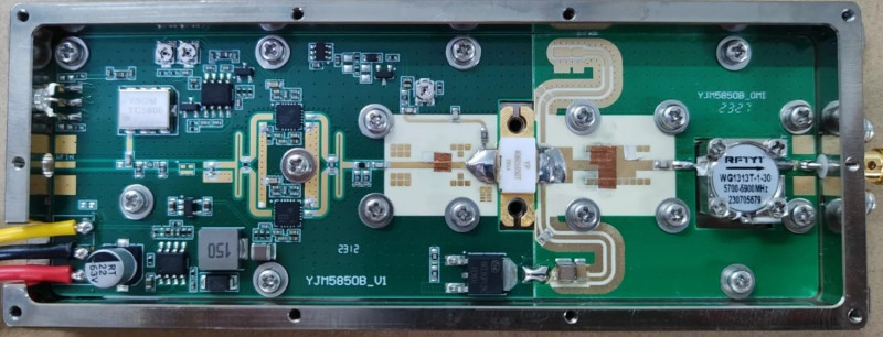
The PA:
Well nowadays it is not really hard to find PA’s in the 50 =>100W range for 6cm. The one I found is the YPM5850C. It is a jammer for 5.8GHz drones. It is available on different sources on the net. The specification is 47dBm out with 42dB gain.
The jammer function is the VCO to the upper left. Of course, needs this to be removed.
From data sheet:
Innotion’s YP40601650T is a 50-watt, internally matched gallium nitride (GaN) high electron mobility transistor (HEMT) designed specifically with high efficiency, high gain and wide bandwidth capabilities, which makes the YP40601650T ideal for multiple applications with frequency from 4400MHz to 6000MHz.
I could not get more than 45.08dBm out (with my measurement uncertainty) which yields 32.2W out with about 2-3dBm drive. Which makes the specification fair, but not 50W out.
Update, I now have 47dBm out see lower down.
RX is not fully tested. However, the close beacon SK6MHI @ 5760.800 could be read 59 from tree reflections.
A small video:
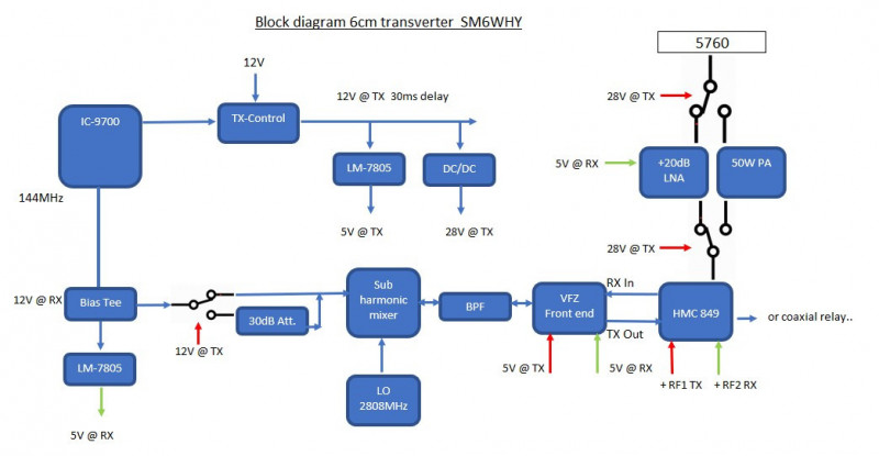
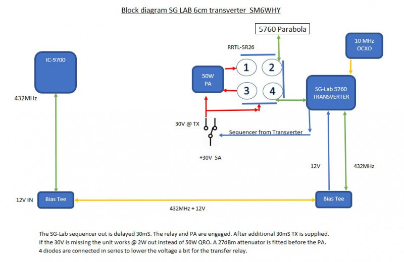
A simple block diagram:
Antenna:
My antenna is a small dish measuring 400x300 and has a gain of 24dBi. This is not so much gain, but the small size makes it easy to install or to bring.
Some success was made and a local beacon was heard. However high loss in the mixer and added LNA started to generate problems in NF and overall gain.
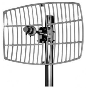
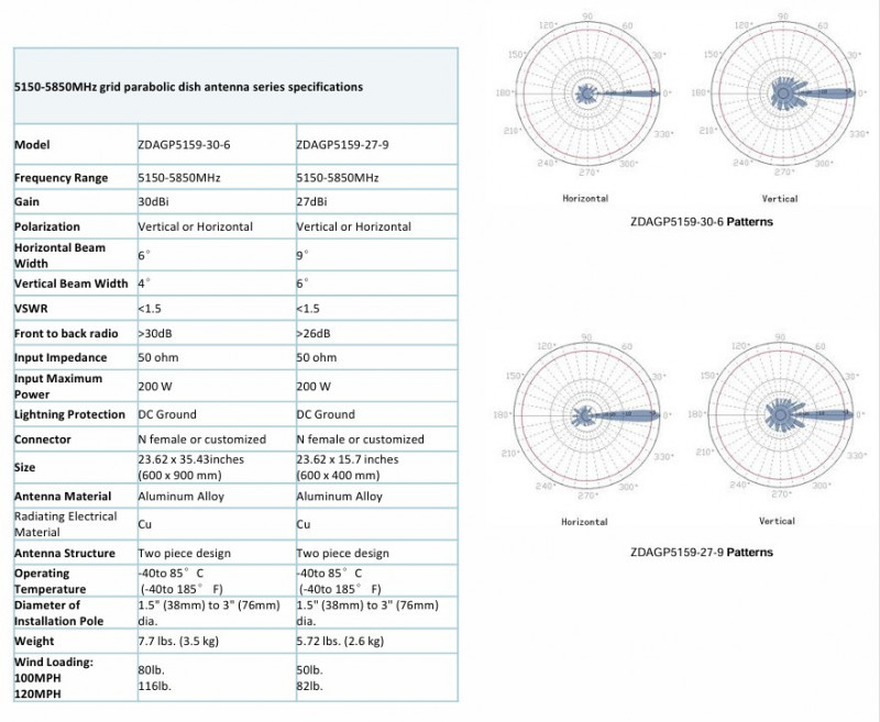
Ideally, I would like the bigger brother of this antenna. And yes, I bought one. A 30 dBi antenna is probably what is needed to reach other stations from my QTH. 900 x 600 is still a quite small antenna.
I need to make a new hole in the roof and mount the 10GHz and 5.7GHz on the elevation rotator. Now it is located close to the other antennas and it is not possible to add one more parabola. However now it is -7 outside and snowing, so this has to wait. (3 January 2026). Finalized 2026-07-05
Second step:
The Bulgarian company SG-LAB has recently made a transverter for 6cm. Their latest version is 1.4.
I have seen tests done comparing this against DB6NT version, and the conclusion from that test was that it is equal good or even better. I say nothing about this since I have not done this test myself.
Pricing is very good for this transverter, currently 288 Euro (late 2025). That is from my own perspective a good price for a transverter @ 5760 with 2W out. (DB6NT 815 Euro, 250mW out).
Some amateurs dislike buying ready build things, and look down on others that do not build everything from scratch. However, I’m not one of those guys. If it is available, why not.
When running without 30V (PA) it will be QRP. The output from the transverter is lowered to about 27dBm, later after TX relay attenuated to about 5dBm which the PA needs. This means an ERP of 300W is available, with no 30V applied.
Simplified schematic, I omitted the bias tee. The transverter operates nice with the VOX and the PA is 30ms delayed.
A small antenna comes with the transverter, with this connected to the now ready outdoor box the beacon SK6MHI could be received in the shack with closed windows and wrong direction. It is located 6km from my QTH. What to say, not bad.
As usual, the common trap is the connectors/pig-tails used when wiring all together. I assumed (totally wrong) that one of my Chinese pig-tail that did not work on 10G would on 5.7G. Well, it did work but the loss was high -1dB for 15cm length.
After the first poor output power measurement, I measured and replaced the worst ones. I needed to cut and re-solder one of them. This can most probably newer be a EME station, but I don’t want to lose any dB unnecessarily.
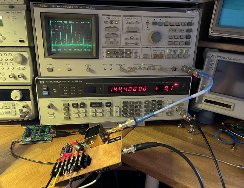
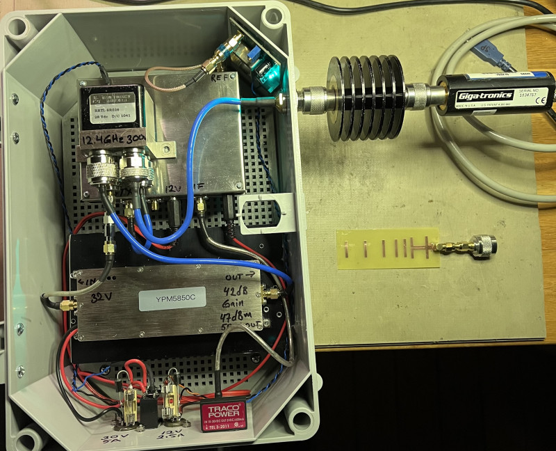
Now 47dBm out -30 dB attenuator connected. Maybe hard to see on the Giga-tronics display.
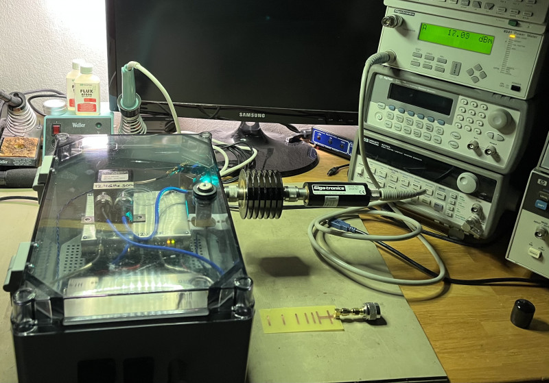
A close-up pic of the box. The small antenna can be seen.
I only trigger the PA from the sequencer and turn 32V on. This is risky business if the bias circuit has flaws.
Giovanni, IN3HOG and IW1EPJ Gianni has done lots of measurements on a PA module. They have seen that the bias circuit isn’t perfect. The 32V is engaged before the negative bias has reached -5V.
I quote Giovanni;
Recently, IW1EPY Gianni and I tested a Chinese PA system from SZHUASHI, marketed as the YPM5850C, which can operate on the 6cm amateur band.
Here are the results of our initial tests:
The bias was strangely factory-set to the minimum negative of -0.5 volts, and therefore the PA consumed so much power when turned on that it tripped the power supply. Fortunately, simply adjusting the trimmer brought it to the recommended current of 0.7 amps.
Vcc = 32 volts, bias current set to 0.7 amps (recommended value by xxxx).
Saturated Power Out = +47.5 dBm (about 50 W), consumption 4.6 Amp, input +10 dBm
Linear Power Out 1 dBcp = +46 dBm (about 40 W), input +8 dBm
Efficiency of 34%, much lower than declared by the Chinese manufacturer or measured by other OMs. (The GaN manufacturer Innotion claims that at the 5800 MHz frequency it has an efficiency of 51%).
The PA's maximum gain was found at 5830 MHz, while at 5760 MHz it drops by 0.8 dB. No conversion has been performed to bring it into our amateur radio band.
It gets very hot.
Although the PA was sold with three wires, one of which is yellow, it arrived with only the two power wires, "Red" (+Vdc) and "Black" (Ground), and without any documentation.
By studying the PCB traces, we saw that the missing yellow wire could have activated the PTT function and should have been soldered to a pad labeled VEN (Volt Enable). The circuit designed for this function is simple and acts by turning off the AP2962 switching IC, so we realized that all that was missing to activate this function was a Schottky diode and a capacitor. Once the two missing components (case 0402) were mounted on the existing free pads, the PTT function worked immediately. Now, simply ground the VEN pin and the PA will turn off. This ability to inhibit the PA is very convenient because it eliminates the need for an external PMOS switch to turn off the amplifier!
The VCO jammer arrived already disconnected and disabled, so nothing had to be done.
Now, let's get to the bad news.
The PA power-up sequence:
When 32 volts are applied, the AP2962 switching IC is immediately started and producing a +5.3 volt supply (this IC can also be locked/activated via the VEN (PTT) pin).
This voltage serves three purposes:
1) The two SE5003L drivers.
2) An LDO IC with a +3.3 volt output used to enable the two drivers by adjusting their VRefs.
3) A DC-DC converter IC that produces a negative voltage of -5 volts, which, adjusted by a potentiometer, is fed to the GaN gate, thus regulating the bias current drawn by the gate.
Downstream of the DC-DC converter, a transistor driven by the presence of -5 volts enables a PMOS that applies the +32 volt supply to the GaN drain.
With this last operation, the PA is now ready to be driven by an external RF signal.
Unfortunately, the activation sequence is not perfect; in particular, the +32 volts applied to the GaN are enabled when the negative voltage has not yet reached -5V, but rather when the negative voltage produced by the DC-DC converter is still at approximately -2.5 volts.
Therefore, upon power-up, even when powered up with the VEN/PTT, a strong and worrying current spike appears in the GaN drain, lasting more than 1 msec, with a downward slope of up to 10 msec. The spike has an intensity greater than 10 Amp (10 Amp is the full scale of the Hall Effect measurement system we used to measure the drain current).
At power-up, there is another very short-duration current spike due to the Miller capacitance between the GaN drain and gate. That is, the +32 volts applied to the drain briefly raise the gate voltage to positive values, and consequently the GaN experiences a dry short.
To visualize this peak, otherwise masked by the previous peak, it is necessary to first power the GaN with a correct and stable bias and only then apply the +32 volt voltage to the drain.
This peak lasts about 1.5 microseconds but is very intense. Unfortunately, this effect is inevitable; it is usually mitigated by keeping the impedance of the negative bias source very low. In this PA, however, the impedance appears too high (about 2 kOhms) and exacerbates this problem.
We are now testing a solution to eliminate or at least mitigate these problems.
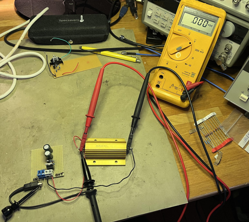
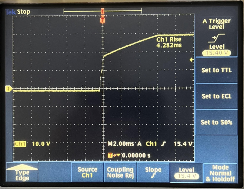
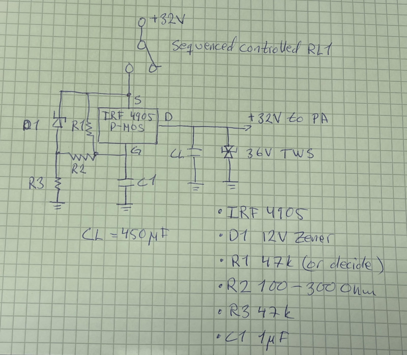
So, here is my (SM6WHY) quick and dirty attempt to try to mild these effects, I’m sure that building a new bias and feed externally is probably best.
32 V soft-start for cheap 5.7–5.8 GHz GaN PA modules (PTT switches the supply) Many low-cost Chinese 5.8 GHz GaN PA modules work well, but when 32 V is switched on at every PTT press, the module can see large turn-on transients. The internal DC/DC converters (including the negative gate-bias supply) need a few milliseconds to stabilize, and a fast drain-voltage step can also couple into the gate through Miller capacitance.
A simple improvement is to add a high-side P-MOSFET after the relay output, with an RC gate network. This forces the PA supply to rise gradually (typically a few milliseconds, depending on the PA input capacitance and wiring), instead of an abrupt 0→32 V step, reducing:
- capacitor inrush current
- stress current through the GaN device at power-up
- Miller-induced gate kick
- relay arcing and contact wear
Key parts (starting values):
- P-MOSFET: IRF4905 (TO-220). Note: tab = Drain; isolate if mounted to chassis.
- Gate series resistor (at the MOSFET gate): 100 Ω
- Gate clamp: 12–15 V zener from Gate to Source (cathode to Source) to limit |Vgs|
- RC soft-start network (self-driven from the same 32 V line):
- R (Gate-node to Source): 10 kΩ (sets ramp time)
- C (Gate-node to GND): 220 nF … 1 µF (larger = slower ramp)
- (Optional) Gate pull-down: 47 kΩ to GND (mainly to define OFF when floating)
- TVS diode (unidirectional) across PA supply (after the MOSFET): 36 V recommended (e.g. SMCJ36A class)
It is a very simple circuit, but with a load of 22 Ohm the ramp time is about 4ms.
Note:
I have not left the first building step, it is fun to build things. However, even SM6VFZ pointed out that it is very difficult to get this right. A good LO and then all other things take time to get right. I’m still testing.
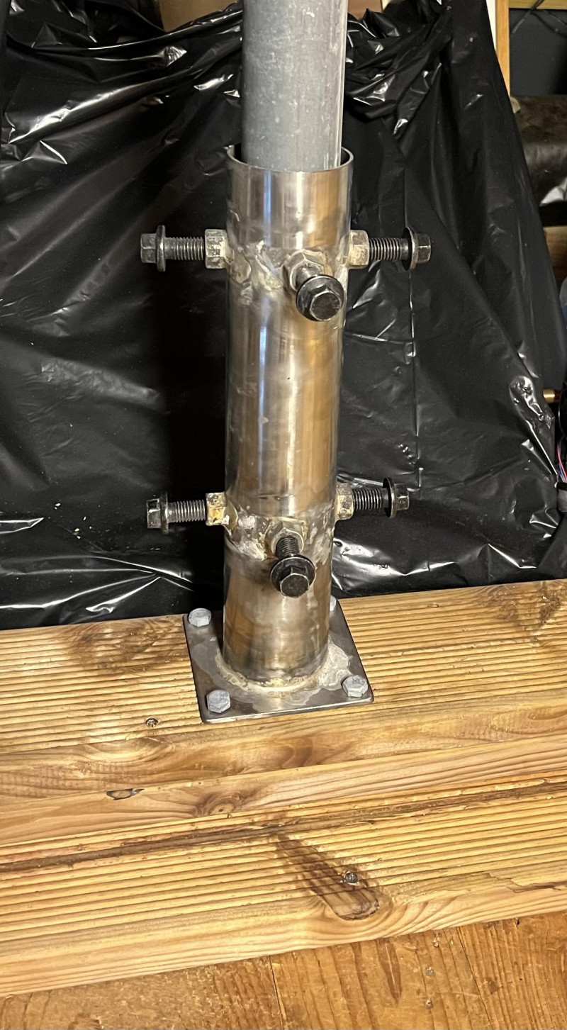
Finally, things on the roof. I made a custom mount for the 50mm mast tube. It can adjust the angles if necessarily.
The 6 cm antenna is now installed on the roof together with the 3 cm dish. The antenna is a 30 dBi grid dish with approximately 6 degrees beamwidth. The PA delivers about 47 dBm, so the theoretical EIRP is around 77 dBm, before feedline (50cm LMR-400) losses.
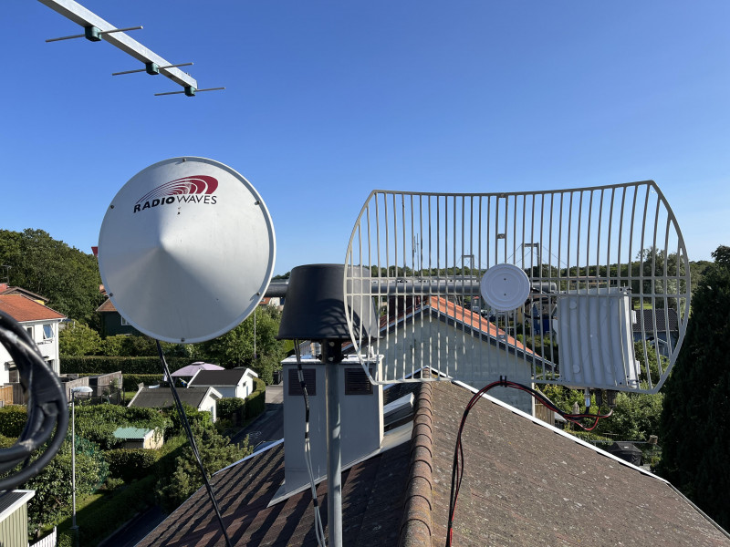
If you have sharp vision you can see Älvsborgsbron behind the grid dish.
As a first real test I could receive the OZ1UHF beacon on 5760.932 MHz. The beacon is located in JO57FH, about 95 km from my QTH, and is listed with 10 W ERP. This is not much power on 5.7 GHz, so hearing it is a good confirmation that the receive chain, LO, transverter, antenna and pointing are working.
The system is still not finished, but this was a very nice first result.
Welcome
Welcome to sm6why.n.nu.

My Newsletter
Links