3cm Project
Well, 3cm is probably as high I will go. On the other hand, you never know.
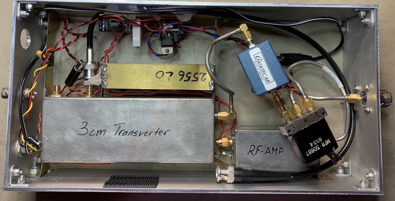
I did build a DB6NT transverter around 2000, it did work however some drift and problems with output power was there. This one has not been widely used by me.
I also made a penny feed for the Lansen nose radar parabolic dish.
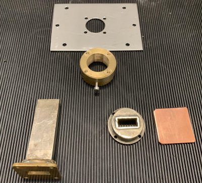
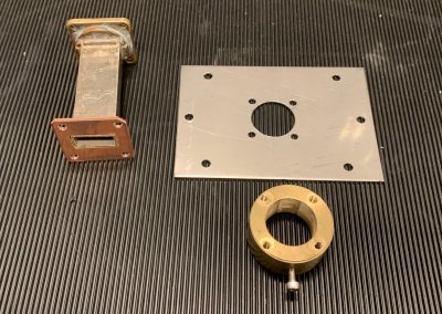
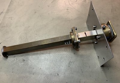
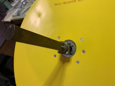
This type of feed has a bad reputation of efficiency. On the other hand, it is popular and simple to build.
Without adjustments with the small screws visible in the picture above the return loss was quite poor. About 13db. The tuning screws should been at the back side, my mistake.
RX was quite nice, probably because the add of the Pre-Amp visible in the first picture. This is a dual stage GaAs fet made by a company called GigaTech in Sweden. I got it from my neighbour Kenneth which also is a radio amateur (SM6DID) and was involved in GigaTech.
Time flies, and there is always new things round the corner.
I live in a urban area and noise is always a problem. HF works good sometimes, 2M has high noise levels in some directions. Now it's time to get 3cm on the roof.
New versions of the DB6NT transverter has been developed during the years, now current is G5.
I found a suitable water proof box, Hammond 1550L. And also, O-ring sealed N-connectors, the power connector is a MS-connector sealed with silicone.
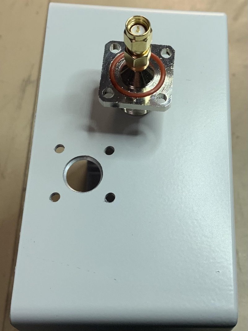
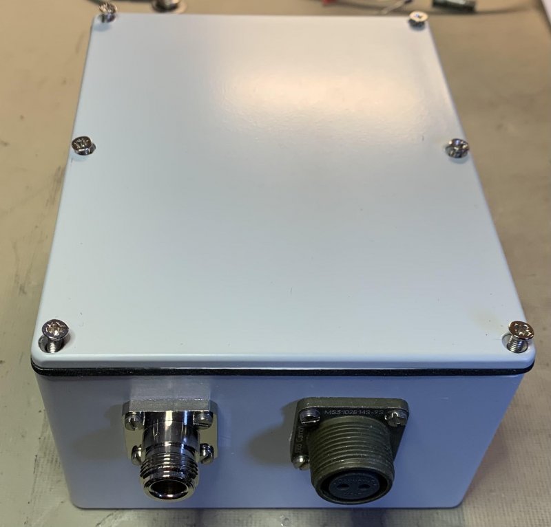
It is recommended that the transverter is mounted on a heat sink. I made one of a piece of 3mm aluminum plate. The plate is hot glued to the box to prevent more drilling in the water proof box.
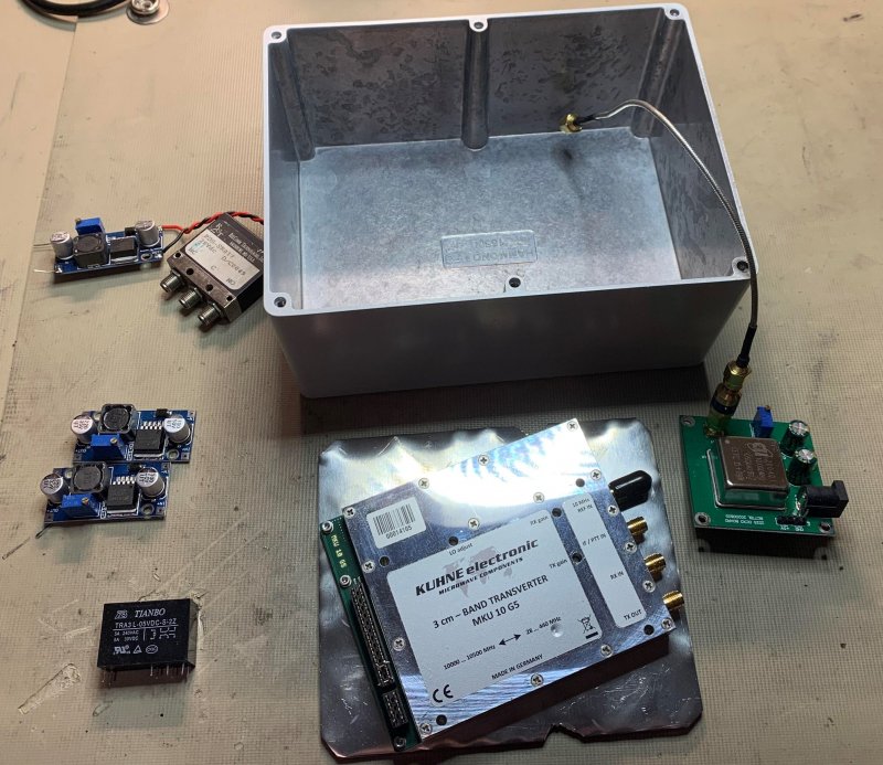
The stability of the transverter is not superb, so an OCXO is added. Some step-up and step-down modules is used for the coaxial relay, OCXO and PA.
I made a simple schematic of the Rx/Tx switching. For the PA control I use a TMR-1221 which is a small dual 5V supply. The -5V will be turned on before the 10V VDD.

The PA is built very simple, and best practice is not 100% followed, however it works. First, I tried a TMD-7185-2, but I could only have gain up to 9GHz. It was actually 0 at 10.368. This was not expected because many uses the RFMA-7185 with success on 3cm.
I found a TMD-1013 which did work, and delivers about 2W with 20db gain. I made a small brass box and soldered the MMIC. The box is mounted on a small heat-sink. Since the PA is on for short periods will this probably be ok. After a while with Tx on it becomes really hot. Before the box was closed, I added pieces of the kind of black foam IC's are usually sticked into. How much damping this does is not known by me. I just took what's in the junk box. I did not see any unstability on the SA.
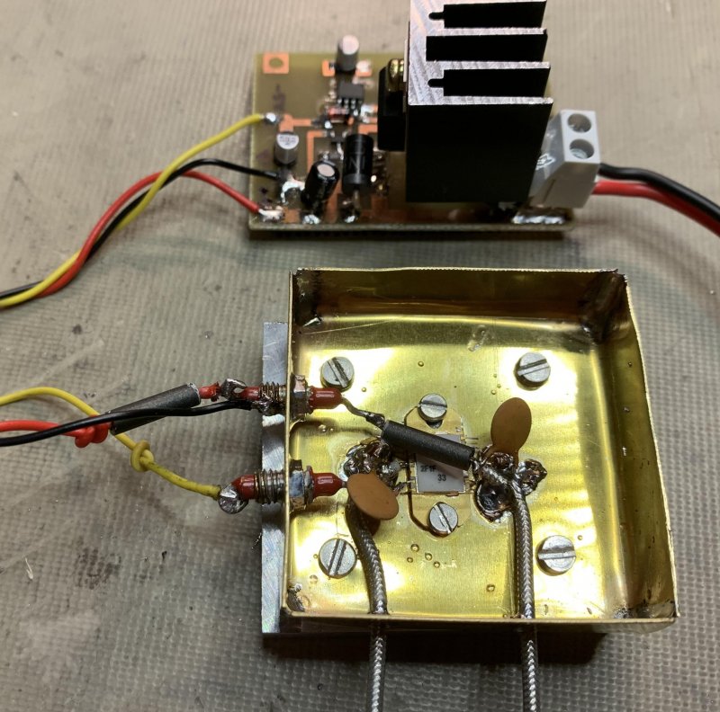
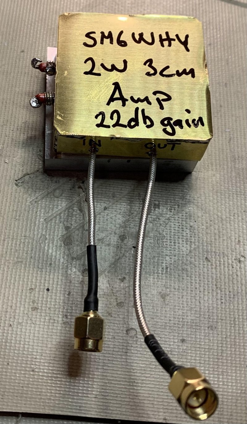
The gain is measured with my recent added analyzer Systron-Donner 809-2.
Thank you Ronny SM7FWZ for letting it go :)
It is an old spectrum analyzer meaning measuring gain has of course some ± db accuracy. An ADF-5355 module is used as signal source.
Edit. Power out is 2W measured with a Hp 432A.
Complete transverter.
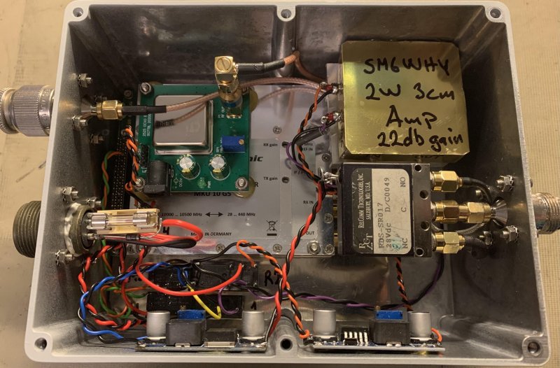
The Lansen parabolic dish with penny feed is not really water proof. I guess it can be, but I will use that one for later portable use, hopefully together with my old DB6NT transverter.
For the roof I will try an offset dish parabola. I selected a quite small (60cm) because it will be mounted together with my other antennas. If my old Ham-2 rotator will manage this will time reveal.
I needed a feed for the offset parabola. I made one that W1GHZ has described.
It is made from brass and a piece of WR-90. A flange mount SMA has the right pin length.
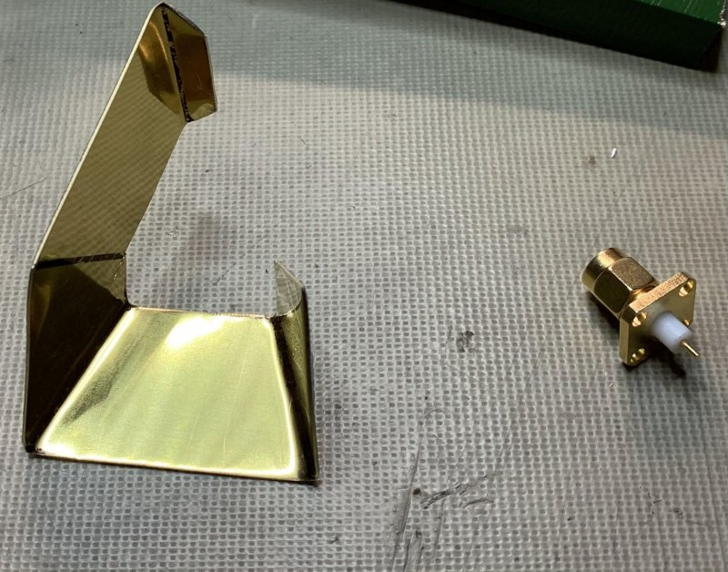
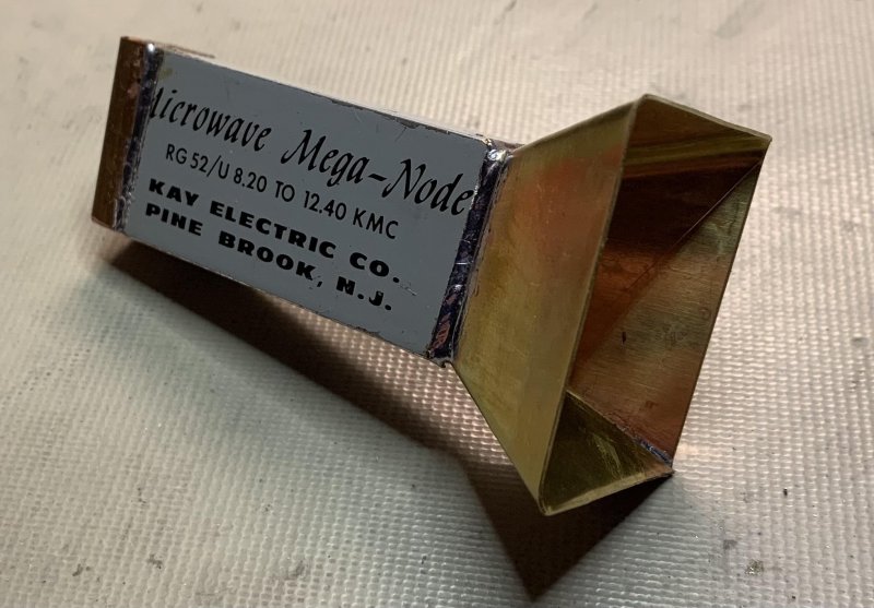
To be able to fixate the feeder in the parabola focal point I use an old LNA. Removed everything inside and only use the housing. The WR is centered and then hot glued in place. The front is covered by a piece of plastic from the lid of a cake can. The RL was measured to 20db @ 10.368GHz.
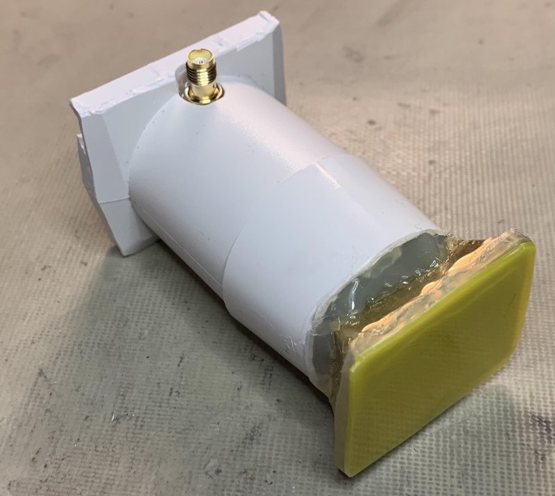
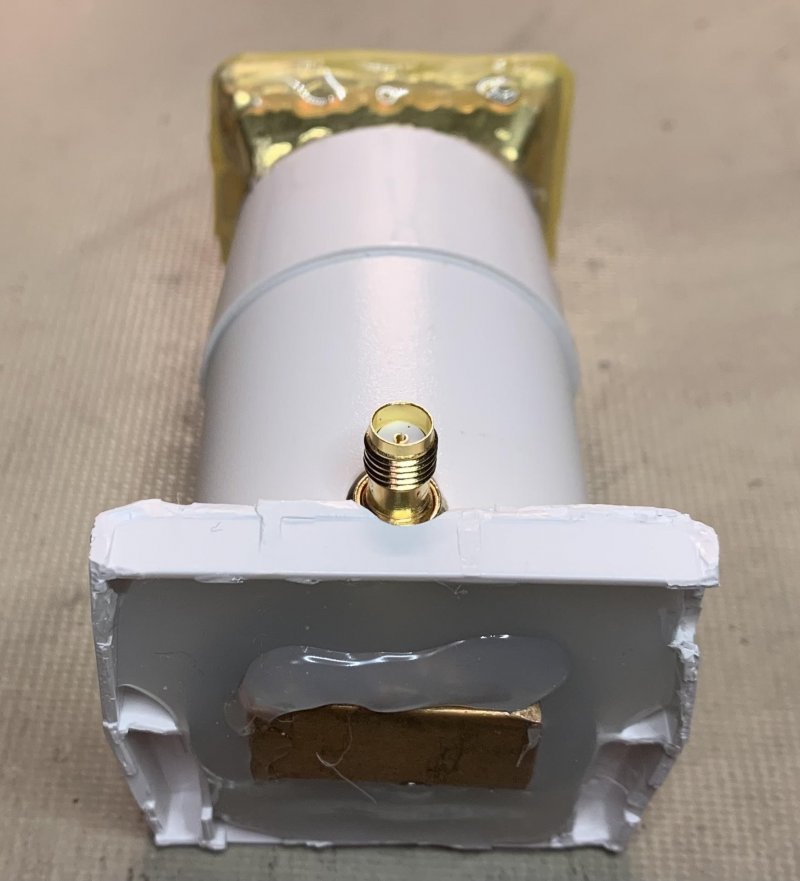
Here in place. If the offset parabola doesn't work good I could try with my penny feed instead.
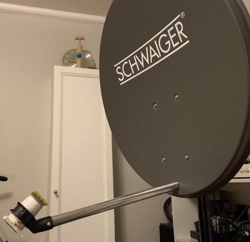
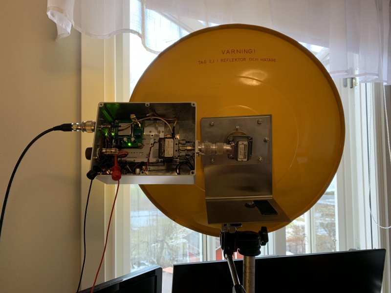
Above antennas works. However, I came across a Radio Waves SP2-10NS. It is a 60cm parabolic dish with Radome. Frequency band is 10.15 to 10.7 GHz, mid-gain is about 34 dBi. It has N-contacts and are ready to go.
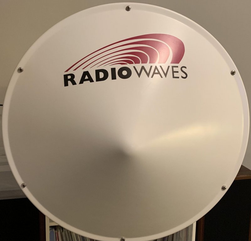
The original mast mount for this antenna is huge. I had to make a custom variant. It is made of clamps for exhaust gas systems, available @ Biltema in Sweden. Not premium, however very cheap.
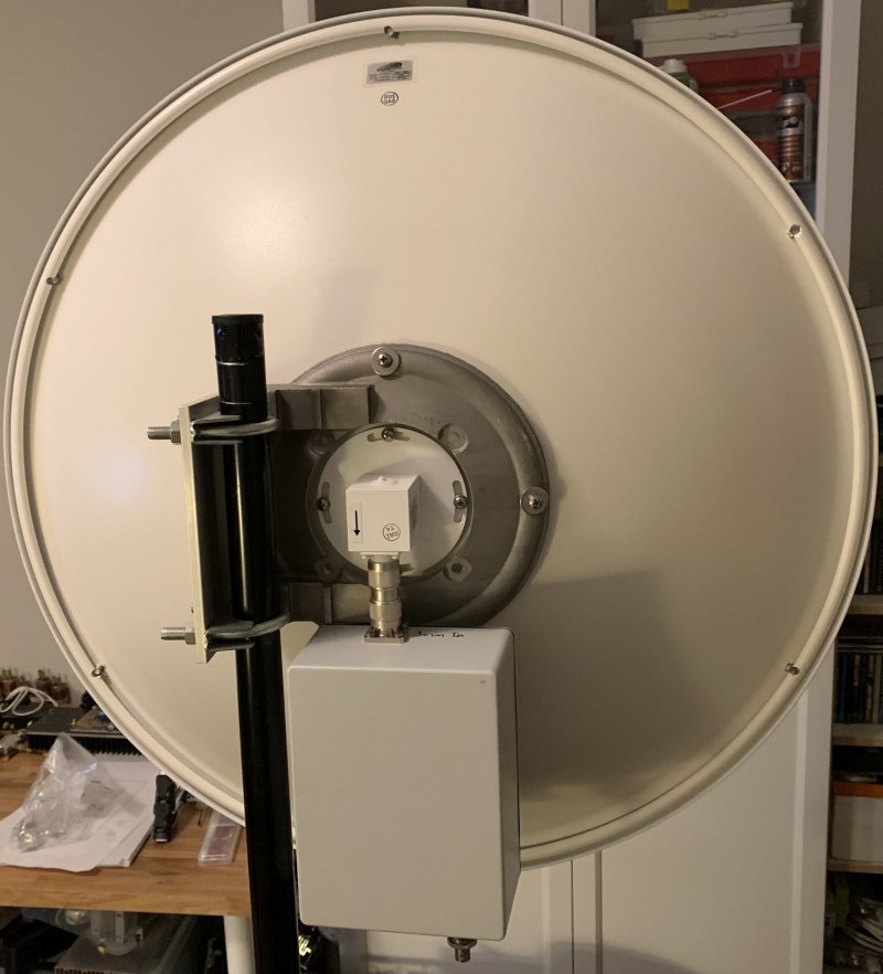
The transverter fits nicely beneath, now mounted on a tripod in the shack. My goal is to have it on my roof. The problem with that is that my QTH isn’t any good. Hopefully I can hear something more than headset noise.
One more box is under construction. It is a PA with pre-amp using the old GigaTech pre-amp made by SM6DID. The PA is made very simple and is not tested yet. It consists of a FLM1011-8F. Best case 1W in 8W out. I say best case because my PA design lack of quality design. I use 2pcs cuts of SU-02 boards soldered to a copper heat spreader. RG-402 is soldered directly to the board, have worked before.
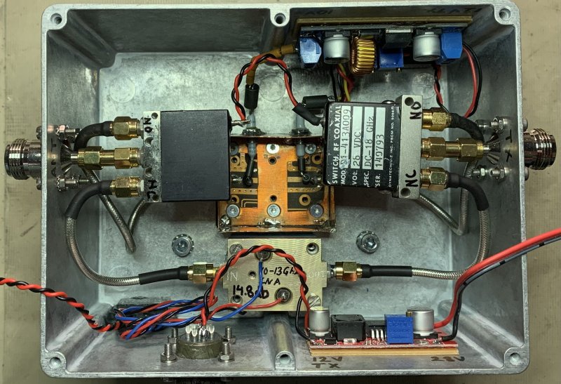
There was no luck with the pre-amp or PA. If a pre-amp is necessarily or not is a wide-open discussion. I decided to try the MKU LNA 102 A2. It has a noise figure of 0.8 and a gain of about 25dB. It is unconditionally stable, the Giga Tech LNA was not. It started to generate noise sometimes. Now I least hear OZ1UHF and SK6WW.
A new PA is also found. It comes from a Harris system. It delivers 5W out and has a gain of 18dB.
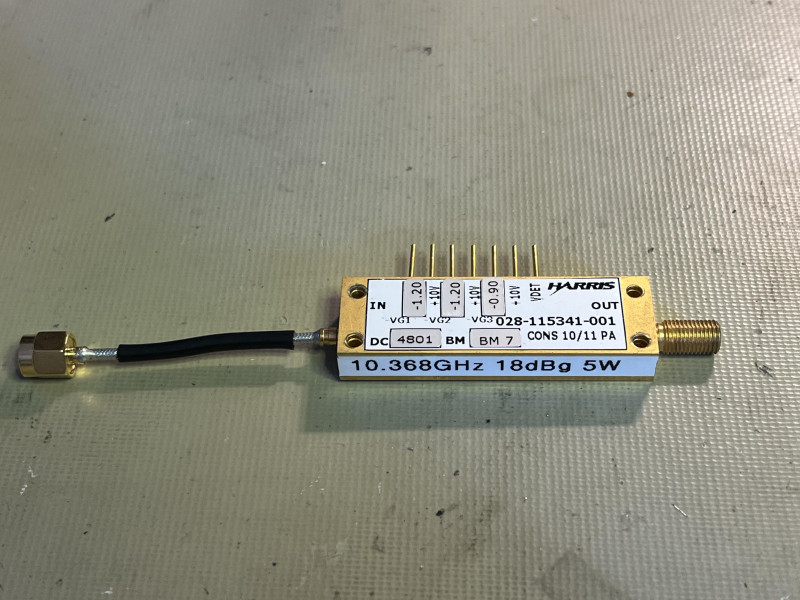
The unit is a 3-stage amplifier and needs 3 different negative bias voltages. A simple bias bord was made, and the negative voltage is generated by a TRACO-1221 dual 5V supply and then adjusted with the trimmers. A quite small heat sink was milled and drilled to create a tight fit to the module.
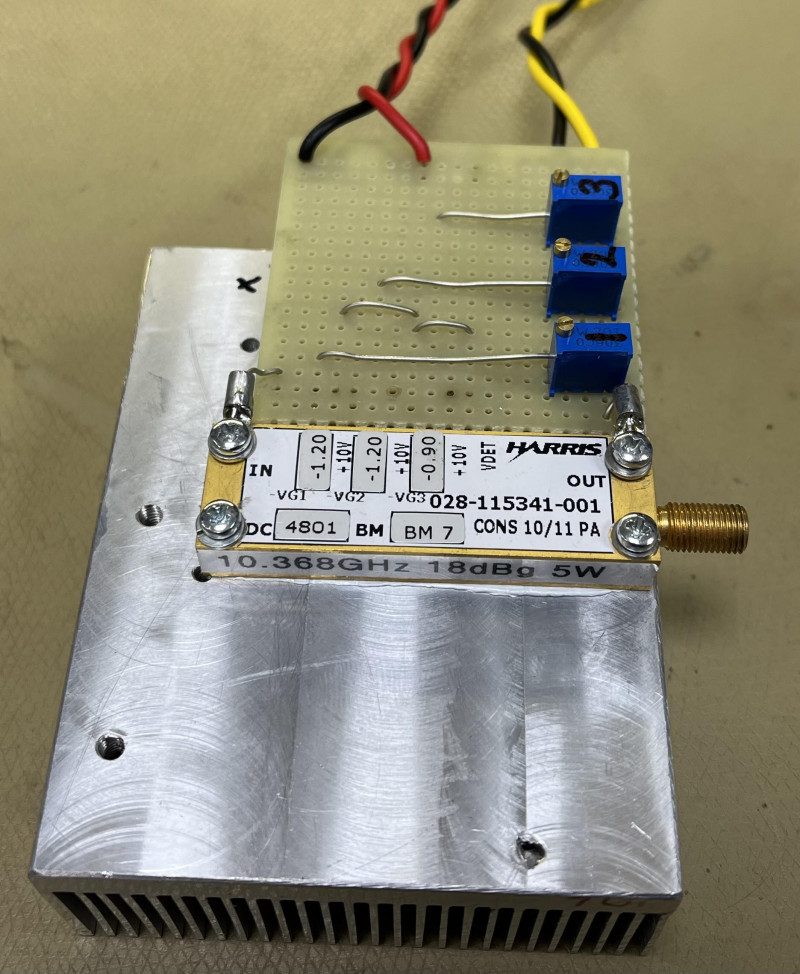
The input connector is a SMP type. An adapter is needed. I mounted a fan on the heat sink and run it on the bench in TX mode for a while, it was ok. These units are made for 100% duty.
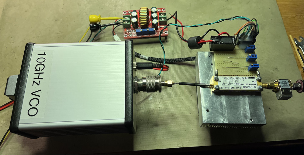
When I connected 10V drain Voltage I noticed that the needle on the HP-432A power meter raised a bit. This means that the unit can have some kind of oscillation. What I know is that this particular units have a circulator on the output. Never the less I mounted a 10GHz circulator to the output and the eventual problem was gone.
18dBg was measured with the HP-432A using my VCO as signal source.
I use a step-down buck to achieve 10V drain Voltage. The PA unit draws about 5A. I selected a 12A step-down and it is cool after several minutes of TX. A relay controls the 10V via the dual 5V bias supply, meaning if no bias is present the drain V can not be set to on.
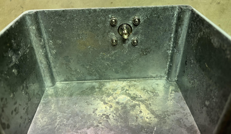
Even though the aluminum enclosure is water tight it began to corrode inside. The reason is not known. Nevertheless, I needed a bigger one to be able to fit the 5W PA.
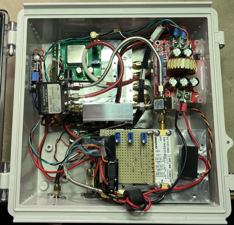
I found a suitable plastic box that measurers 20x20cm. It is made for electrical installations outdoors. Everything was placed inside, and a test run on the bench was a success. +36dBm out included some doubtful Chinese adapters to the attenuators. I’m quite convinced that there is at least 37dBm out. Well, roof mounting next…
The parabola dish is now on a separate SPID rotator. The plan is to put all antennas on the same rotator with a new mast mount.
Transverter in place, waiting for the next NAC. Or if something else comes up.

Karlatornet can be seen in the horizon, not so far from me actually height 246m.

73 de SM6WHY
Lasse

